

Formulas, Examples & Applications
Calculate the maximum bending moment
The maximum bending moment is one of the key parameters in engineering mechanics. Whenever forces act on a beam, a Shaft another component, internal stresses are generated, which are described by the bending moment. Anyone who wants to design components safely and realistically evaluate loads cannot ignore this parameter.
On this page, we explain how to manually calculate the maximum bending moment, which formulas apply depending on the support conditions and loads, and what to pay particular attention to in practice. For simple applications, manual calculation is often sufficient. However, for more complex load cases, multiple loads, or code-compliant design verifications, a software solution is usually the significantly fasterand more reliableapproach.
What is the maximum bending moment?
The bending moment describes the internal stress in a component resulting from external forces. It occurs when forces act perpendicular to the component’s axis, causing deflection or bending stress. The maximum bending moment corresponds to the point of highest stress. It is precisely at this point that it becomes clear whether a component is adequately dimensioned or whether critical stresses are present.
This parameter is particularly important in mechanical engineering because it is directly linked to the subsequent design of components. An incorrect assessment can either lead to under-design—and thus a safety risk—or to unnecessarily heavy and uneconomical designs.
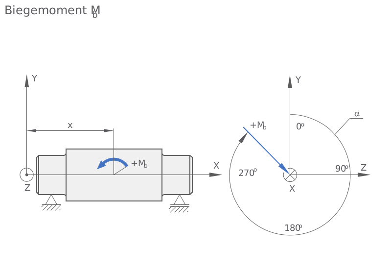
The figure shows a schematic representation of the bending moment acting MbM_b acting on a supported component. On the left side, a beam is shown on which a positive bending moment acts, causing deflection. The coordinate axes illustrate the spatial orientation of the system.
On the right, the bending moment is also shown in terms of angle. This illustrates how the moment acts around the axes and within what angular range it occurs. This analysis is particularly relevant for Shafts more complex components where loads do not act in a single plane.
Formulas for calculating the maximum bending moment
The maximum bending moment always depends on the support conditions and the type of load. Therefore, it is crucial to first identify the correct load case. Even small discrepancies in the assumptions can lead to significantly different results.
For a simply supported beam with a single load at its center:
Here, F represents the applied force and L represents the length of the beam.
In a cantilever beam with a load at the free end, the maximum bending moment is greater because there is no second support to relieve the load. In this case, the following applies:
For a uniformly distributed load, the result is:
Here, q denotes the line load over the entire length of the component.
In practice, it is crucial to select the correct load case. Even small deviations can lead to significantly different results.
Formulas for calculating the maximum bending moment
To illustrate this principle, let’s consider a simply supported beam with a central force of 1,000 N and a length of 2 meters. Substituting these values into the formula yields:
The maximum bending moment is therefore 500 Nm and occurs at the center of the beam. This is exactly where the stress is highest.
Calculate the maximum bending moment directly
Enter the force and beam length. The calculator immediately determines the maximum bending moment for a simply supported beam with a single load at its midpoint.
Result – Formula:Mmax = (F · L) / 4 Note: This calculator is intended for a simply supported beam with a single load at its midpoint.
Efficiently calculate complex load cases Try it for free with no installation required: For real-world applications involving multiple load cases, Shafts code-compliant verification, we recommend using professional calculation software.
Try it for free
Calculate the maximum bending moment directly
Enter the force and beam length. The calculator immediately determines the maximum bending moment for a simply supported beam with a single load at its midpoint.
Note: This calculator is intended for a simply supported beam with a single load at its midpoint.
Try it for free with no installation required: For real-world applications involving multiple load cases, Shafts code-compliant verification, we recommend using professional calculation software.
Try it for freeRelationship between bending moment and stress
In practice, the bending moment alone is not sufficient to fully evaluate a component. The decisive factor is the resulting stress in the material. This is determined by the ratio of the bending moment to the section modulus:
σ=World Cup
This illustrates why the maximum bending moment is so important in the design process. It forms the basis for calculating the bending stress and, consequently, for strength verifications. Anyone who uses incorrect load assumptions, unit errors, or inappropriate simplifications at this stage risks either component failure or unnecessarily high material and manufacturing costs.
! Avoiding Common Mistakes in Practice
In theory, the formulas often seem simple, but errors frequently occur when applying them. Incorrect assumptions about bearing conditions or load cases are particularly critical. Units are also often confused, which can lead to significant discrepancies.
Another common issue is the failure to account for safety factors. However, these are essential—especially in real-world applications—to reliably prevent component failure.
Avoiding Common Mistakes in Practice
In theory, the formulas often seem simple, but errors frequently occur when applying them. Incorrect assumptions about bearing conditions or load cases are particularly critical. Units are also often confused, which can lead to significant discrepancies.
Another common issue is the failure to account for safety factors. However, these are essential—especially in real-world applications—to reliably prevent component failure.
Efficient Calculations in Practice
For simple standard cases, the maximum bending moment can easily be calculated by hand. However, as soon as multiple load cases, real-world installation conditions, notch effects, combined loads, or code requirements need to be taken into account, manual calculations quickly reach their limits.
Calculation tools such as MDESIGN it MDESIGN to calculate bending moments systematically and efficiently, incorporate various load conditions into the design, and link results directly to strength verifications. This not only saves time but also enhances the traceability and reliability of the calculation.
In practice, documenting the results is also particularly important. In addition to the calculations themselves, reliable verification, traceable calculation logs, and clear technical documentation play a central role. Those who regularly design components therefore benefit from a solution that not only performs calculations but also documents the results in a structured manner and makes them available for verification purposes.
Frequently Asked Questions
How do you calculate the maximum bending moment?
The maximum bending moment is calculated using different formulas depending on the load case. For a simply supported beam with a single load at its midpoint, for example: Mmax = F · L / 4.
Where does the maximum bending moment occur?
The maximum bending moment occurs at the point of highest bending stress. In the case of a simply supported beam with a centrally located load, it is usually at the center; in the case of a cantilever beam, it is at the fixed end.
Why is the bending moment so important?
The bending moment is the basis for calculating bending stresses and, consequently, for the safe design of structural components. It helps to realistically assess loads and reliably perform strength analyses.