Gearbox calculation for
technical leadership
Develop multi-stage gears holistically from the very beginning
From the initial concept to detailed tooth flank optimization, MDESIGN supports the complete calculation and design of complex gear systems. With the expert modules MDESIGN gearbox and MDESIGN LVR/LVRplanet, multi-stage gears, shafts, bearing arrangements, and gearings can be modeled, analyzed, and optimized in a seamless workflow.
The integrated combination of calculation, 3D modeling, variant analysis, and standard-compliant verification reduces development effort and enables rapid optimization processes—from preliminary development through to detailed design ready for production.
Standards taken into account for Gearings, Shafts , and Lager
Gear geometry
DIN ISO 21771
Gear Load Capacity
DIN 3990/3991 ISO 6336/10300
Shaft Load Capacity
DIN 743
Rolling & Plain Bearings
DIN ISO 281 DIN 26281 DIN 31652/31653
Establish standards, accelerate engineering
MDESIGN provides a consistent basis for calculations across the entire team. Structured data entry, centrally maintained calculation bases, and consistent documentation ensure that results remain traceable and comparable across projects.
For over 40 years, MDESIGN has been helping companies calculate and design technical components—today with more than 35,000 users worldwide.
Calculate gearings, shafts, and bearings together
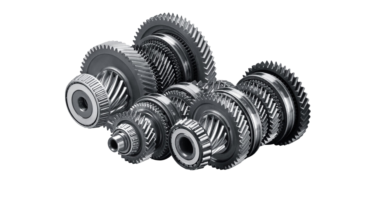
In a multi-stage gears, each stage influences the subsequent components. Gear ratios alter rotational speeds and torques; tooth forces act on shafts and bearings; and deformations, in turn, affect the load distribution during tooth engagement. MDESIGN integrates these relationships within a single assembly. The output includes, among other things, power flow, gear ratios, gear pair loads, bearing reactions, shaft stresses, load-carrying capacities, as well as efficiency and power loss. This not only reveals whether individual components are adequately sized; design engineers can also see how changes affect the entire system and where an adjustment will yield the greatest benefit.
Examine load distribution and tooth contact more closely
A sufficient calculated load-carrying capacity does not automatically guarantee favorable load distribution across the tooth width and engagement length. Shaft deformations, bearing deflection, gear body stiffness, and manufacturing tolerances can significantly alter the contact conditions.
MDESIGN LVR can be used to analyze line load, foot stress, flank pressure, contact temperature, and tooth stiffness for spur gear stages. For planetary gearsets, LVRplanet expands the analysis to include load distribution among the planets, ring gear deformation, the planet carrier, and other system-specific factors.
This makes it possible to identify critical contact areas even before the Manufacture . Edge modifications or design changes can be applied in a more targeted manner, rather than being adjusted only after test bench or prototype testing.
Develop complete gears in a 3D model
Visually build transmission structures, identify technical relationships, and prepare calculations directly from the model.
Gears, shafts, bearings, and gearings are modeled in a unified environment, automatically linked, and calculated directly.
Changes to the geometry, gear ratio, or bearings have a direct impact on the entire system and can be evaluated immediately.
Try it for freeUnderstanding results and targeted further development of transmission variants
The results integrate kinematics, gearings, shafts, bearings, and load distribution into a comprehensive picture. This reveals whether, for example, tooth contact, shaft deformation, bearing life, or installation space limit the design .
Based on this, translations can be modified, part positions can be repositioned, gear meshing parameters can be adjusted, or flank modifications can be analyzed. The effects can then be re-evaluated across the entire assembly.
This shortens development cycles and helps accelerate the transition from a functional prototype to a technically optimized transmission design.
|
01
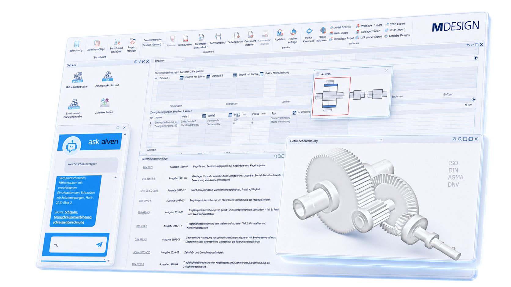
Guided interface and system overview
Structured input fields, help texts, and technical notes assist in configuring gear stages, Shafts, bearings, and operating data. An AI assistant helps answer questions during the calculation. Results are presented clearly.
|
02
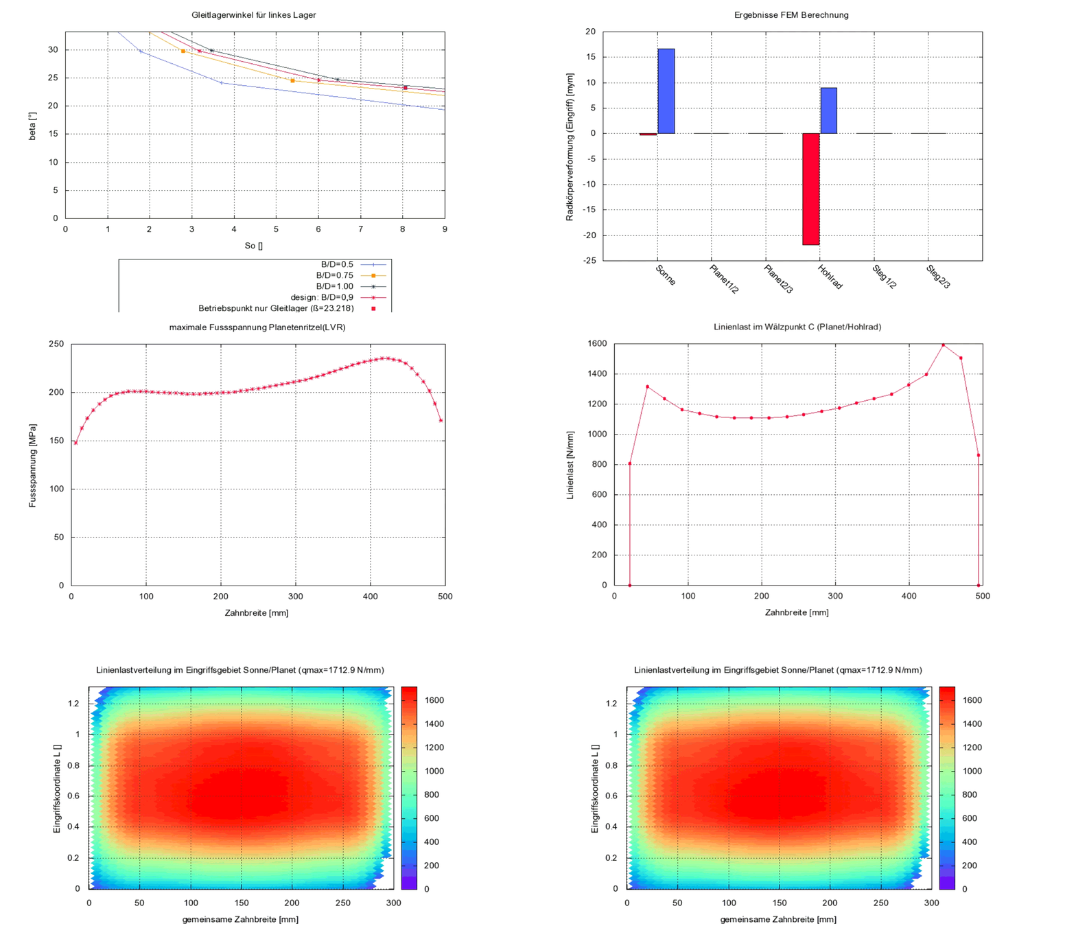
Automatically generated charts
Graphical representations help users understand load distribution, tooth contact, kinematics, and other relationships in the Gears. Diagrams make complex calculation parameters easier to visualize and facilitate technical interpretation.
|
Documentation and proof at the touch of a button
Automatically generate technical documentation.
All input data, standards, boundary conditions, results, and graphics are automatically compiled into a complete set of documentation. This results in transparent verification documentation for internal development, customers, testing organizations, or manufacture.
STEP export directly from the calculation
Components are modeled, analyzed, and evaluated in MDESIGN. The validated results can then be exported directly as STEP files and transferred to CAD systems. This ensures that the entire development process remains consistent—without any data discontinuities or the need for manual geometry transfer.




Features of the gear calculation tool
The functions are organized into compact sections based on standards, gear types, design, overall verification, gear tooth verification, shafts, bearings, and load distribution.
-
Standards & calculation bases
- DIN ISO 21771
- DIN 3990
- ISO 6336
- DIN 3991
- ISO 10300
- DIN 743
- DIN ISO 281
- DIN 26281
- DIN 31652
- DIN 31653
- Calculation based on the literature (Baumann, Hohrein)
-
Transmission types & gear ratio combinations
- Spur gears
- Planetary gearset
- Bevel gear drive
- Hypoid gearbox
- Multi-stage gears
- Internal gears
- External gears
- Straight-tooth gears
- Helical gears
- Double-helical gears
- Simple planetary gear set
- Stepped planetary gearbox
- Combination of bevel, spur, and planetary gears
-
Design & variants
Input values
- Axle configuration
- Selecting a combination of levels
- Number of steps
- Complete translation
- Partial translation: Bevel gear stage
- Partial translation: Spur gear stages
- Partial translation: Planetary gear Sstages
- Drive power
- Drive speed
- Design safety factor for tooth flank
- Design safety factor for tooth root
- Design life of the gearing
- Number of design variants
- Optimization goal
Output values
- Designed transmission variants
- Step combination
- Partial translations
- Number of teeth
- Module
- Axle spacing
- Tooth widths
- Mass
- Volume
- Installation space
- Inertia
- Safeties tooth flank and tooth root
-
Overall calculation for the transmission assembly
Input values
- Drive shafts
- Wave sections
- Pairs of wheels
- Input and output shafts
- Rotational speeds
- Torques
- Services
- Application factor
- Impact factor
- Oil temperature
- Ambient temperature
- Type of lubrication
- Gears-Lubricant
Output values
- Kinematic ratio
- Static translation
- RPM and Torque
- Power flow
- Wheel pair loads
- Transmission mass
- Shaft speeds
- Tooth engagement frequencies
- Bearing reaction forces
- Roller bearings rollover frequencies
Sample results chart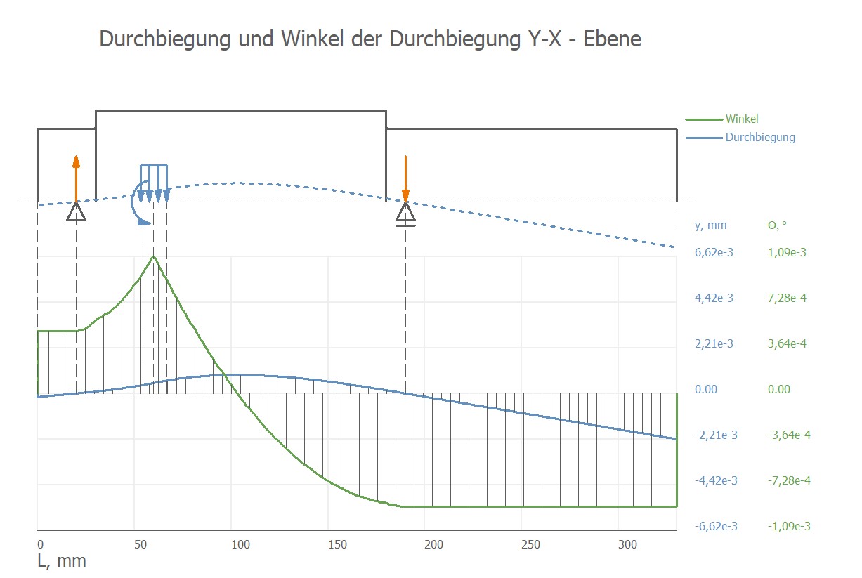
An example of a graphical analysis of a transmission assembly showing deflection and the angle of deflection. -
Gear meshing & load capacity verifications
Input values
- Type of gear meshing
- Number of teeth
- Standard module
- Angle of engagement
- Bevel angle
- Wheelbase or axle angle
- Profile shift
- Tooth width
- Gear quality
- Material
- Torque
- Rotational speed
- Application factor
- Load distribution factor
Output values
- Pressure on the flanks
- Tooth-root tension
- Safety Factor: Edge Pressure
- Safety Factor: Tooth Root Fracture
- Protection against jamming
- Expected service life
- Dynamic factor
- Width factors
- Frontal factors
- Axial Force on the rolling circle
- Radial force at the rolling circle
- Circumferential force
-
Shafts & mountings
Input values
- Shaft geometry
- Wave sections
- Notch shapes
- Material
- Bearing locations
- Fixed bearing
- Non-locating bearing
- Thrust bearing
- Rolling bearing type
- Type of plain bearing
- Radial and axial loads
- Required Service Life
- Required structural safety
Output values
- Safety against yielding
- Safety against permanent failure
- Deflection
- Angle of twist
- Bending moment
- Torsional moment
- Reference voltage
- Bearing forces
- Rated service life
- Structural safety
- Minimum lubricating film thickness
- Storage temperature
-
Load distribution in a spur gear set
Input values
- Up to four gear ratios
- Gear parameters
- Tool Data
- Torque or tangential force
- Shafts- and inventory data
- Ring elasticity
- Profile modifications
- Width modifications
- Flank deviations
- Flank topology
Output values
- Linear load distribution
- Foot pressure distribution
- Pressure on the flanks
- Contact temperature
- Tooth stiffness
- Torsional stiffness
- Flank width factor
- Width factor at the tooth base
- Load distribution across the tooth width
- Load distribution along the cut section
- Shaft deformations
- Bearing deflections
- Wheel deformations
- Ring elasticity
Sample results chart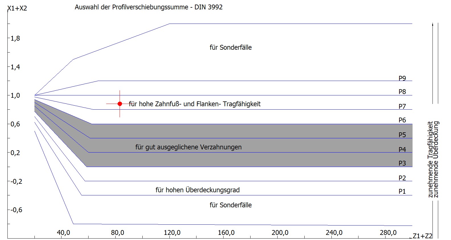
An illustrative graphical analysis of a spur gear. -
Load distribution in planetary gearsets
Input values
- Simple planetary gear set
- Stepped planetary gearbox
- Number of planets
- Power and RPM at the drive
- Sun, planet, and ring gear
- Planetary bearing
- Rolling bearings or plain bearings
- Wheel body stiffnesses
- Bearing stiffness and bearing clearance
- Planetary carrier
- Tolerances for center-to-center distance and web spacing
- Modifications and deviations
Output values
- Load distribution between the sun and the planet
- Load distribution: Planetary gear/ring gear
- Load distribution factor Kγ
- Width factor KHβ
- Pressure on the flanks
- Contact temperature
- Foot tension
- Cyclic tension distribution in a gear ring foot
- Rotational deviation
- Tooth stiffness
- Wheel body and web deformations
Sample results chart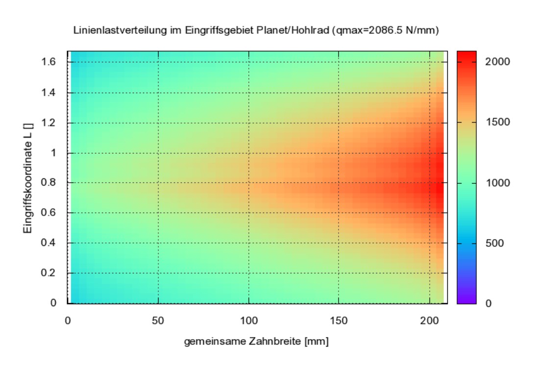
An illustrative graphical analysis of a line load distribution in the meshing area of a planetary gear and ring gear. -
Flank modifications & optimization
- Head retraction
- Lifting the foot
- Final acceptance
- Headrest removal
- Vertical curvature
- Wide roundness
- Profile beveling
- Flank line angle modification
- Profile angle deviation
- Flank line angle deviation
- Wear on the inlet
- Division deviation
- Importing measured edge topologies
- Proposal for flank line angle correction
-
Lubrication & temperature
- Immersion lubrication
- Injection lubrication
- Oil temperature
- Ambient temperature
- Kinematic viscosity
- Density
- Feeding temperature
- Flank temperature before the procedure
- Arithmetic edge-centered roughness
- Thermal conductivity
- Specific heat capacity
- Contact temperature
Try it for free – Your access to MDESIGN
Discover for free
Learn about the features
Just get started
No download, no installation
Full range of services
14 days of access to all sections