
Bolted joint calculation
for Maximum Technical Safety
Get more out of every screw connection
It is not the screw alone that determines the reliability of a connection. Only when preload, friction, components, assembly, and actual operating loads all interact does it become clear just how resilient the design really is.
MDESIGN makes these exact relationships predictable. This allows you to identify early on what works, where there is room for improvement, and which adjustments will optimize the design. Compliant with VDI 2230 or Eurocode 3.
Establish Standards, accelerate Engineering
MDESIGN provides a consistent basis for calculations across the entire team. Structured data entry, centrally maintained calculation bases, and consistent documentation ensure that results remain traceable and comparable across projects.
For over 40 years, MDESIGN has been helping companies calculate and design technical components—today with more than 35,000 users worldwide.
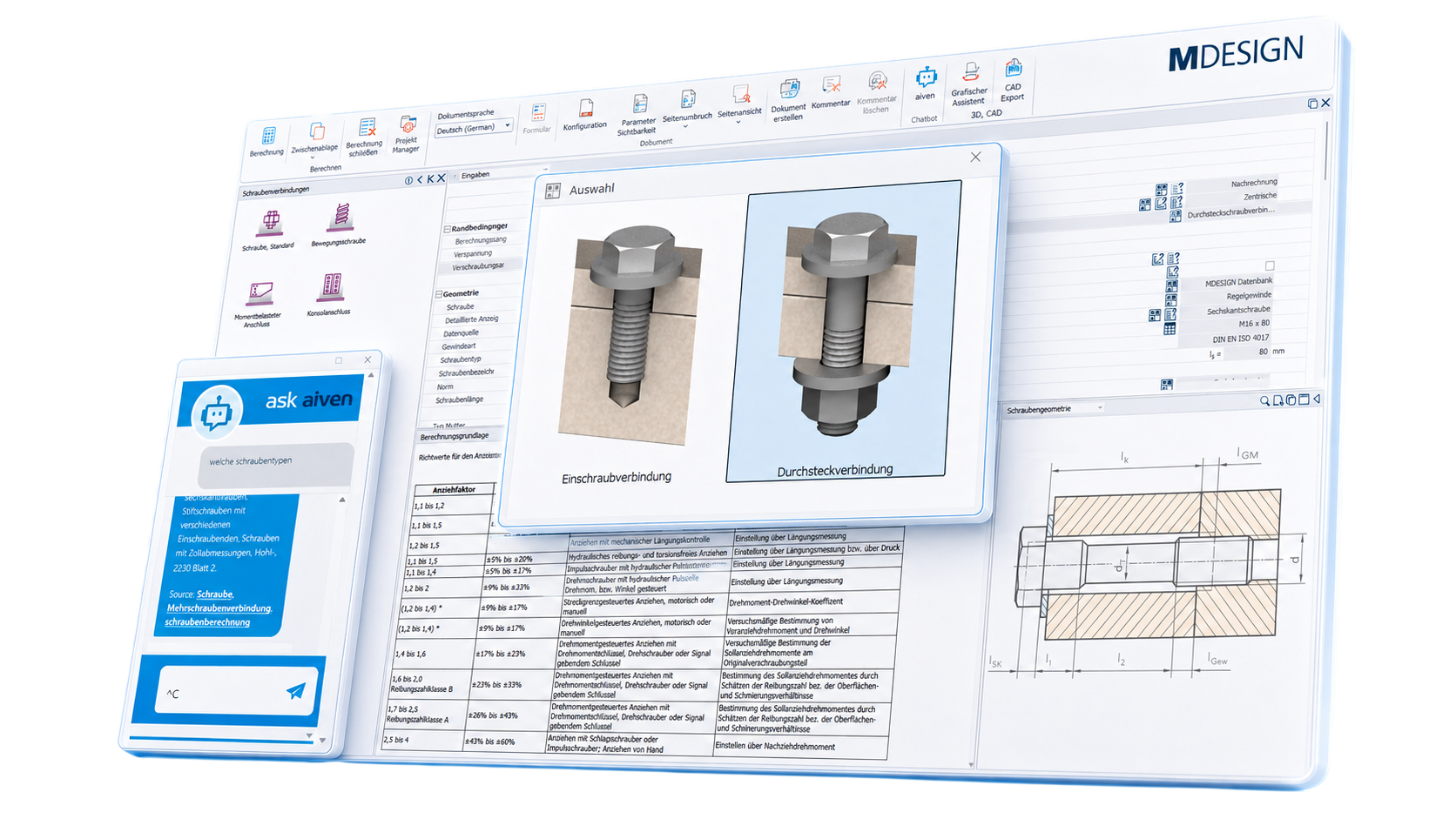
Calculate bolted joints under realistic conditions
A reliable bolt calculation takes more than just the bolt itself into account. Component geometry, materials, coefficients of friction, assembly conditions, temperatures, and external loads also influence the behavior of the joint. This allows critical load conditions to be identified early on and different design variants to be compared in a targeted manner. MDESIGN also makes it possible to tailor bolted connections specifically to the actual Design and its operating conditions. In addition to existing material data, users can enter their own material properties for bolts, plates, and locking elements.
Material Data for More Reliable Decisions
The load-bearing capacity of a bolted joint does not depend solely on the bolt. The clamped components, washers, and nuts also determine how forces are distributed and what load limits apply.
MDESIGN provides comprehensive material data, including relevant properties such as tensile strength, yield strength, and interfacial pressure.
Custom materials, internal properties, and company-specific material data can also be added and used centrally. This creates a unified database for recurring calculations and company-wide standards.

Understand Results and Refine Designs Systematically

01
Automatically Generated Charts
Key metrics, tables, and charts show which factors influence the connection and where there is potential for optimization. This allows for more targeted adjustments and faster technical evaluation of design variants.
|
02
Intuitive 3D Modeling
The 3D model directly displays the geometry, force application, and direction of loading at the joint. This makes it easier to assess how changes to the structure, preload, or loading will affect the system—and which variant makes the most sense for further development.
|
Documentation and proof at the touch of a button
Automatically generate technical documentation.
All input data, standards, boundary conditions, results, and graphics are automatically compiled into a complete set of documentation. This results in transparent verification documentation for internal development, customers, testing organizations, or manufacture.
STEP Export directly from the Calculation
Components are modeled, analyzed, and evaluated in MDESIGN. The validated results can then be exported directly as STEP files and transferred to CAD systems. This ensures that the entire development process remains consistent—without any data discontinuities or the need for manual geometry transfer.




Features of the MDESIGN Screw Calculation Tool
The most important calculation modules are listed individually. For each key application, the main input values and the results calculated from them are shown side by side.
01
Calculation Bases & Standards
Calculation of fastening and motion screws based on standards and the literature.
Calculation Bases & Standards
Calculation of fastening and motion screws based on standards and the literature.
Depending on the calculation module, the appropriate guidelines, standards, and technical principles are used.
02
Screw Connections According to VDI 2230
Detailed calculations for centrally and eccentrically loaded bolted joints.
Screw Connections According to VDI 2230
Detailed calculations for centrally and eccentrically loaded bolted joints.
The calculation systematically models the force, deformation, and preload conditions of a single-bolt connection.
Input values
Calculated Results
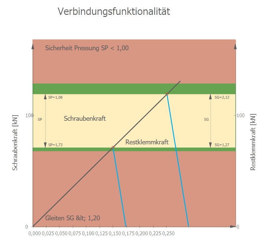
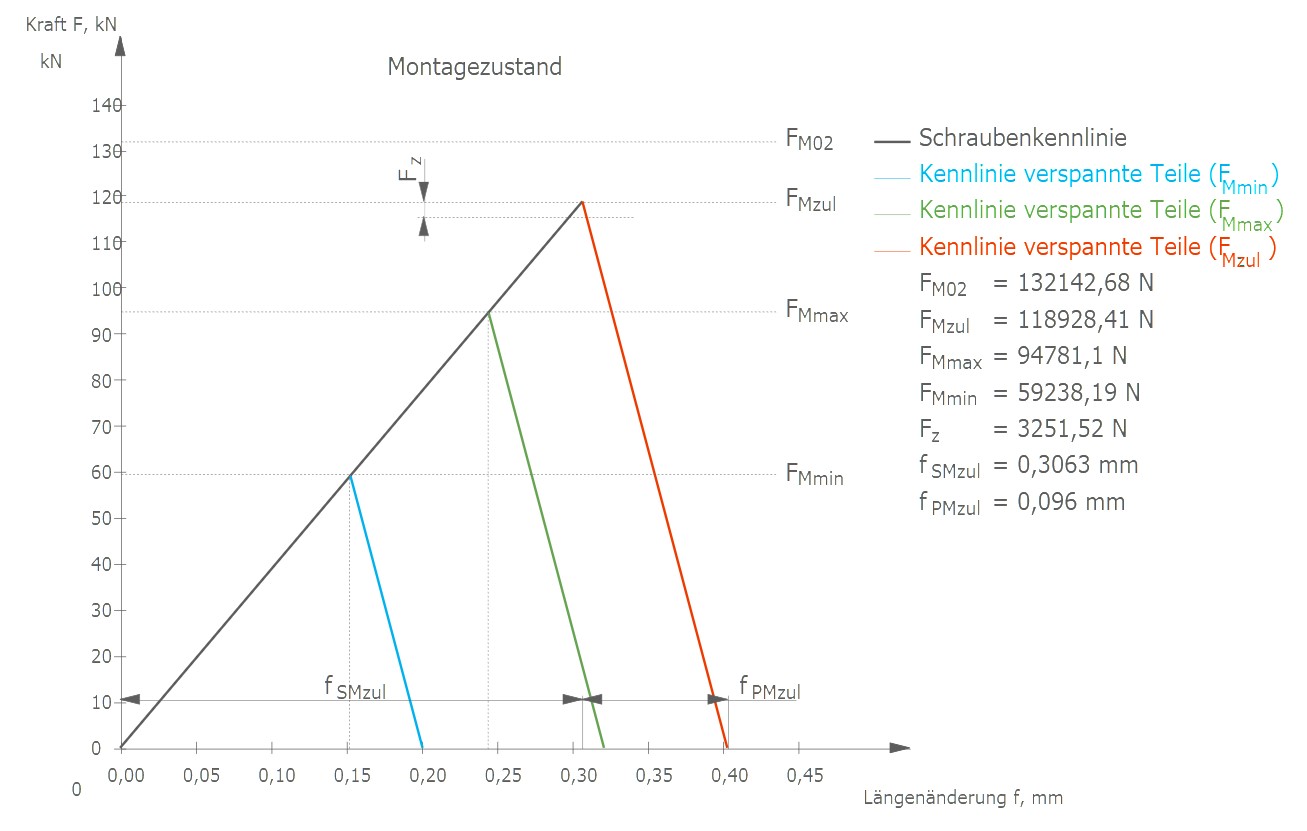
Two examples from among several available result graphs.
03
Bolted Joints in Steel Construction
Verification of shear-, tensile-, and sliding-resistant connections in accordance with Eurocode 3.
Bolted Joints in Steel Construction
Verification of shear-, tensile-, and sliding-resistant connections in accordance with Eurocode 3.
Steel structure connections are rated according to categories A through E, as well as permissible combinations of shear and tensile connections.
Input values
Calculated Results
04
Console Connections
Calculation of cantilever-type bolted connections under bending, tensile, and shear loads.
Console Connections
Calculation of cantilever-type bolted connections under bending, tensile, and shear loads.
The contact force generates a bending moment about the center of pressure, as well as a transverse stress distributed evenly across the screws.
Input values
Calculated Results
05
Adjustable screws
Design and Verification of Trapezoidal and Sawtooth Threaded Screws.
Adjustable screws
Design and Verification of Trapezoidal and Sawtooth Threaded Screws.
Adjustable screws are calculated for compression, torsion, buckling, flank compression, self-locking, and efficiency.
Input values
Calculated Results
06
Screw Types & Fastener Geometries
Standard and custom screws, as well as various connection assemblies.
Screw Types & Fastener Geometries
Standard and custom screws, as well as various connection assemblies.
The screw geometry can be taken from standard data or specified on a project-by-project basis.
07
Materials & Properties
Material data for screws, nuts, washers, and preloaded components.
Materials & Properties
Material data for screws, nuts, washers, and preloaded components.
Strength and temperature parameters are taken into account depending on the screw, component, and calculation module.
08
Assembly
Determination of all necessary installation parameters, as well as documentation and monitoring.
Assembly
Determination of all necessary installation parameters, as well as documentation and monitoring.
09
Results & Analyses
Technical evaluation of forces, stresses, prestress, and load-bearing capacity.
Results & Analyses
Technical evaluation of forces, stresses, prestress, and load-bearing capacity.
The output results depend on the screw type, the joint, and the selected verification method.
Try it for free – Your access to MDESIGN
Discover for free
Learn about the features
Just get started
No download, no installation
Full Range of services
14 days of access to all sections
Frequently asked questions about screw design
Answers to important questions regarding the design of bolted joints, VDI 2230, and the calculation of preload, residual clamping force, and tightening torque.
Which standard is used to calculate bolted connections?
High-stress screw-in and through-hole connections in mechanical engineering are often designed in accordance with VDI 2230, Part 1. MDESIGN supports structured design and the necessary verifications based on the guideline.
What dimensions are determined in a bolt design calculation?
Key findings include installation preload, minimum preload, residual clamping force, additional bolt force, tightening torque, bolt stresses, surface pressures, and the required safeties.
What is the residual clamping force of a bolted joint?
The residual clamping force is the clamping force that remains under the operating load and after accounting for relevant losses of preload in the connection. It must be sufficiently high to ensure that the seam remains closed and the connection fulfills its function.
Can MDESIGN calculate the required tightening torque?
Yes. The required tightening torque is determined, among other factors, by the target preload force, the screw geometry, the installation method, and the assumed friction coefficients.
Are settlement losses and temperature changes taken into account?
Yes. Installation processes, surface conditions, different materials, and temperature changes can affect the prestressing force. These factors can be taken into account in the calculation and evaluated together.
Can we use our own screws and materials?
In addition to existing geometry and material data, custom screw geometries and company-specific material properties can also be added and used in the calculation.
Does MDESIGN provide a complete list of screws?
MDESIGN compiles input data, calculation bases, results, safeties, and graphical analyses into a transparent set of technical documentation. This documentation can be used, among other things, for development, approval, customer documentation, and quality assurance purposes.