Shaft calculation for safe
products from the start
Shafts Design, identify load limits, and verify strength
Shafts They transmit torque and forces between the components of a drive system. Bending, torsion, notches, mounting conditions, and varying loads determine whether the Design can withstand the required operating conditions over the long term.
MDESIGN allows you to create geometric models of Shafts and shafts and evaluate them according to DIN 743, the FKM guideline, or ANSI. Strength analyses, deflections, bearing reactions, and critical speeds provide a solid foundation for design, approval, and technical documentation.
Establish Standards, accelerate Engineering
MDESIGN provides a consistent basis for calculations across the entire team. Structured data entry, centrally maintained calculation bases, and consistent documentation ensure that results remain traceable and comparable across projects.
For over 40 years, MDESIGN has been helping companies calculate and design technical components—today with more than 35,000 users worldwide.

Keeping Track of the Overall Shaft Load
When designing, it is not just a single stress that matters. Forces, moments, bearing locations, notches, and changes in cross-section influence the stress distribution along the entire geometry. Axial and radial forces give rise to bearing reactions, shear forces, and bending and torsional moments. In addition, deflection, torsion, natural frequencies, and critical rotational speeds are determined. Static and dynamic Safeties show whether the selected design can withstand the required loads. This makes it possible to identify which locations are critical, what safety margins exist, and where diameters, transitions, or bearing arrangements should be adjusted.
Strength Calculation According to DIN 743
DIN 743 is one of the established standards for the static and dynamic design verification of Shafts and shafts. In addition to the load, it also takes into account component geometry, notch effects, surface condition, and size effects.
For relevant sections of the " Shaft ," the values of Safeties are determined for fatigue failure and yielding, as well as for stresses resulting from tension/compression, bending, and torsion. Form factors, support factors, and notch factors are incorporated into the evaluation.
This makes it possible to determine whether a cross-section is sufficiently dimensioned or whether a design change is necessary.
Defining Geometry, Materials, and Loads in a Structured Manner

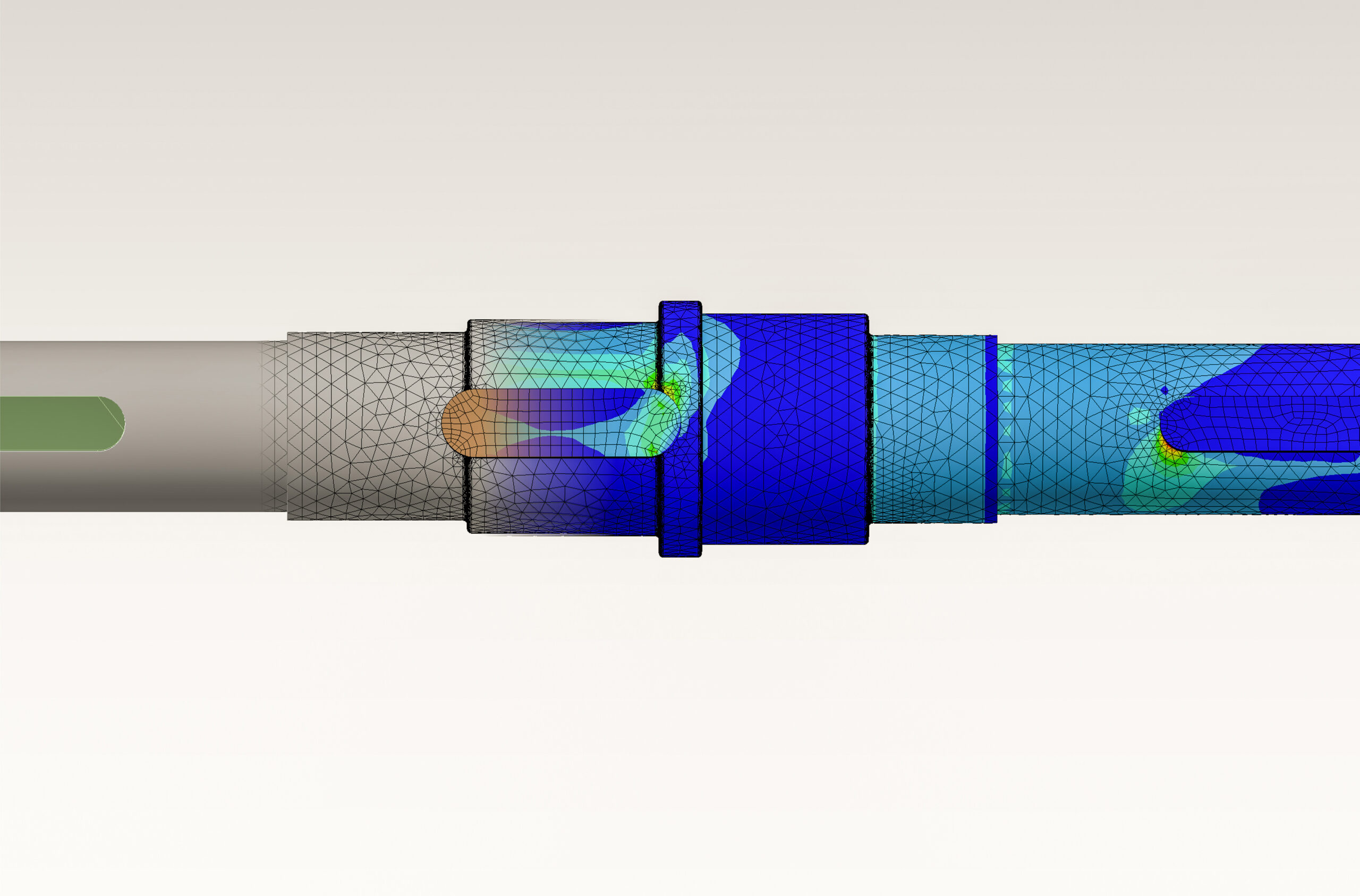
Steps, grooves, holes, press fits, or Gearings alter the stress distribution and must be taken into account in the correct position. The shaft geometry can therefore be designed with different cross-sections and notch shapes or imported via STEP from an existing CAD model.
Bearing locations, forces, moments, power, and rotational speeds are stored in the model. Bearing stiffnesses, self-weight, and gyroscopic effects are also available for further calculations.
MDESIGN includes standardized data sets in accordance with DIN 743-3, containing the relevant strength and elasticity parameters, to assist with material selection. Users can add their own materials and company-specific values and save them for future calculations.
This results in a computational model that integrates geometry, material, and loading into a single framework.
Understanding Results and Further Developing " Shafts " in a Targeted Manner
After the calculation, stresses, safety factors, bearing forces, moment curves, deflections, and other verification parameters are available. Their distribution along the Shaft shows which cross-sections or notches determine the Design .
Critical areas can be specifically mitigated through design changes—such as adjusting diameters, transition radii, notch geometries, or altering the bearing arrangement.
In addition to simply verifying structural strength, the results also aid in the design and comparison of different variants.

01
Automatically Generated Charts
Output graphs show stress, moment, strain, and safety factor curves along the Shaft. This allows critical areas and notable trends to be quickly identified.
|
02
3D model with loads and results
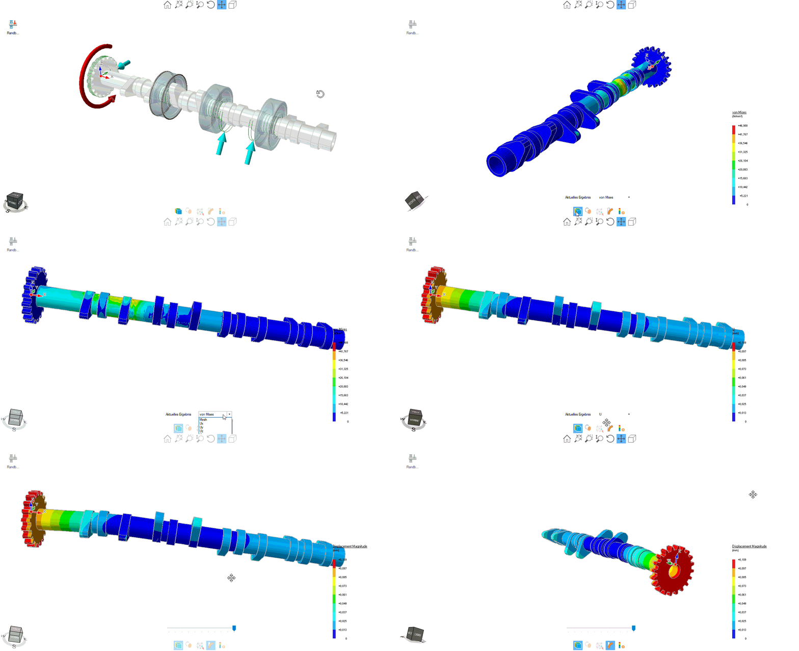
Forces, stresses, and critical areas are visible on the 3D model of the Shaft . This makes it easier to map the calculation results to the geometry and supports the design evaluation.
|
Shaft- Calculate and design hub connections
In drive technology, the reliable transmission of torque is crucial. In addition to the Shaft itself, Shaft hub connections must therefore also be designed to be reliable.
MDESIGN enables the calculation and evaluation of different connection types and integrates them directly into the overall analysis of the Shaft.
This allows for the safe design not only of the Shaft but also of the entire transmission system.

Documentation and proof at the touch of a button
Automatically generate technical documentation.
All input data, standards, boundary conditions, results, and graphics are automatically compiled into a complete set of documentation. This results in transparent verification documentation for internal development, customers, testing organizations, or Manufacture.
STEP Import Directly from the CAD Model
Existing geometries are imported directly from the CAD model into MDESIGN . Using the STEP import, the relevant component geometries are immediately available for further calculation and analysis. There is no need for manual modeling — geometry, calculation, and results remain linked in a seamless digital process.




Features of the " MDESIGN " Wave Calculation
The functions are organized by calculation methods, shaft geometry, bearings, loads, strength analyses, and material properties.
-
Standards & Calculation Methods
- DIN 743
- FKM guideline
- ANSI
- Calculation Based on the Literature
-
Shaft Geometry & Notch Shapes
- Full waves
- Hollow Shafts
- Wavy Heels
- Conical fillets
- Cylindrical shaft shoulder
- Heel with openwork stitching
- Round groove
- Cross Drilling
- Pointed notch
- Rectangular groove for retaining rings
- Keyway
- Press fit
- Splined Shafts
- Serrated shafts
- Gear shafts with involute teeth
- Surface roughness
- Individual Notch Factors
-
Mountings & Loads
Input values
- Fixed Bearing
- Non-locating bearing
- Axle bearing
- Location of the Bearing Seats
- Radial bearing stiffness
- Axial forces
- Radial forces
- Line Loads
- Bending Moments
- Torsional moments
- Input and Output Power
- Rotational speed of the Shaft
- Type of Load: Tension/Compression
- Type of Load: Bending
- Type of Stress: Torsion
- Maximum Load Factor
Output values
- Axial bearing reaction force
- Radial bearing reaction force
- Shear Force Distribution
- Bending Moment Curve
- Torsional Moment Curve
- Tensile-Compressive Force Curve
- Deflection Curve
- Angle of deflection
- Angle of rotation of the Shaft
- Critical Bending Speeds
-
Strength Verification According to DIN 743
Input values
- Calculation Run
- Load case
- Required number of load cycles
- Minimum safety factor against permanent failure
- Minimum safety factor against permanent deformation
- Tensile-Compressive Loading
- Bending load
- Torsional stress
- Material Strength Values
- Diameter used for heat treatment
- Surface Hardening
Output values
- Notch Efficiency Ratios
- Supporting figures
- Formula numbers
- Safety against permanent failure
- Protection Against Leakage
- Tensile-Compressive Stress
- Bending stress
- Torsional stress
- Reference Voltage
- Tensile-Compressive Fatigue Life
- Bending Fatigue Life
- Torsional Fatigue Life
- Technological Scale Factor
- Geometric Size Influence Factor
- Overall Factors
- Critical positions along the Shaft
-
Shaft Design According to the FKM Guideline
Input values
- Principal stresses
- Standard voltages
- Shear stresses
- Medium voltages
- Breakdown voltages
- Tension
- Number of load cycles
- Effective Diameter
- Component Dimensions
- Surface roughness
- Temperature
- Operating Time at Temperature
- Material Properties
Output values
- Tensile Strength of Components
- Yield Strength of a Component
- Component Heat Resistance
- Component Hot Elongation Limit
- Component Creep Strength
- 1% Time-Strain Limit of the Component
- Static Strength Assessment
- Material Change Strength
- Static Utilization Rate
- Cyclical Capacity Utilization Rate
- Overall Safety Factor
- Safety, Fatigue Strength
-
Shaft Design According to ANSI
Input values
- Segment length
- Section Diameter
- Sales radius
- Inventory Items
- Straight-tooth and helical gears
- Rotational speed of the Shaft
- Desired Probability of Survival
- Design factor
- Tensile Strength
- Yield strength
- Surface Condition
Output values
- Calculation Diameter of the Shaft Sections
- Torque
- Bending Moment
- Shear stress
- Concentration factor
- Bearing Reactions
- Transmission forces
- Torque Curve
- Shear Force Curves
- Bending Moment Curves
-
Combined Loading & Mohr's Circle
Input values
- Normal stress along the x-axis
- Normal stress along the y-axis
- Shear stress
Output values
- Maximum main voltage
- Minimum principal stress
- Maximum shear stress
- Average normal stress
- Main Level
- Angle of Maximum Shear Stress
- Direction of rotation
- Mohr's Circle
- Main tensioning element
- Maximum shear stress element
-
Materials & Properties
- Materials According to DIN 743-3
- General-purpose unalloyed structural steel
- Fine-grained structural steel suitable for welding
- Quenched and tempered steel
- Tool steel
- Nitriding steel
- Stainless steel
- Cast steel
- Ductile iron
- Cast iron with lamellar graphite
- Molded Cast Iron
- Worked aluminum alloy
- Cast aluminum material
- Proprietary Materials
- Tensile Strength
- Yield strength
- Flexural Fatigue Strength
- Tensile-Compressive-Alternating Strength
- Torsional Fatigue Strength
- Modulus of elasticity
- Thrust Module
Try it for free – Your access to MDESIGN
Discover for free
Learn about the features
Just get started
No download, no installation
Full Range of services
14 days of access to all sections