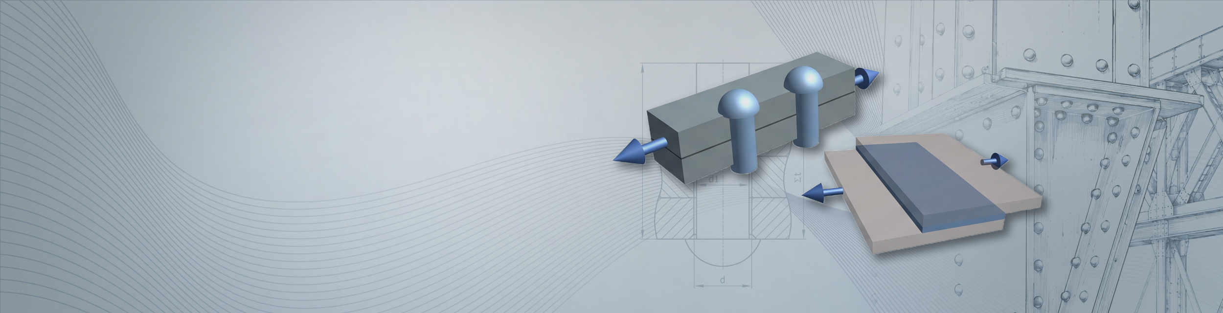
Soldering and Riveted joints with
More potential in every Design
Determine the appropriate dimensions for rivets and Soldering joints , reliably assess stresses
, and document technical results in a transparent manner.
Use joining techniques specifically where they can best demonstrate their strengths
Riveting and Soldering joints are particularly useful when thin-walled parts, temperature-sensitive components, or special manufacturing conditions limit the use of traditional joining methods.
MDESIGN Supports the calculation of typical riveted and Soldering joints , from sizing to strength verification. This allows users to more quickly assess suitable joint types, evaluate loads in a targeted manner, and make more informed comparisons of design alternatives.
Establish standards, accelerate engineering
MDESIGN provides a consistent basis for calculations across the entire team. Structured data entry, centrally maintained calculation bases, and consistent documentation ensure that results remain traceable and comparable across projects.
For over 40 years, MDESIGN has been helping companies calculate and design technical components—today with more than 35,000 users worldwide.
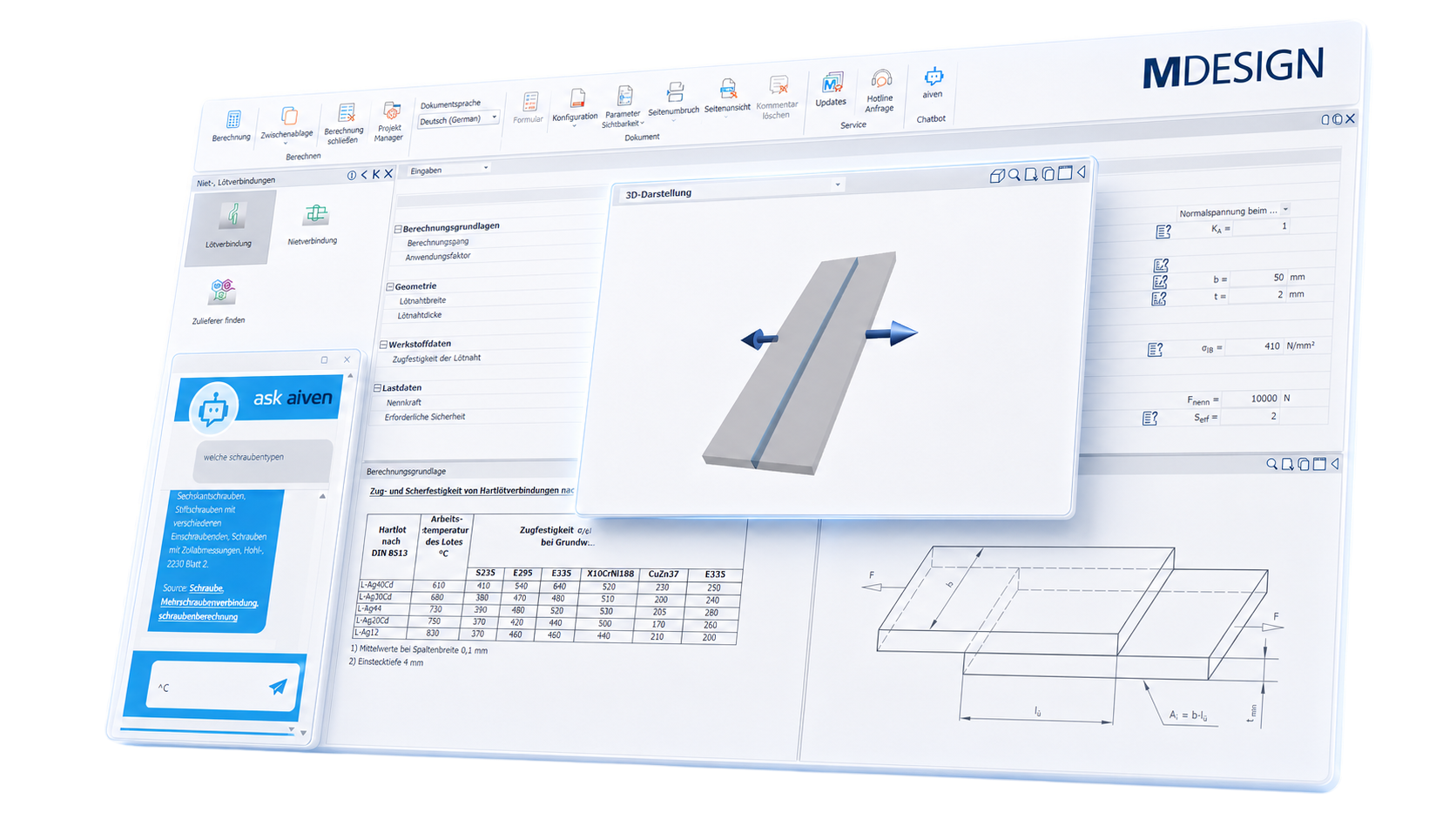
Determine dimensions and load-bearing capacity directly
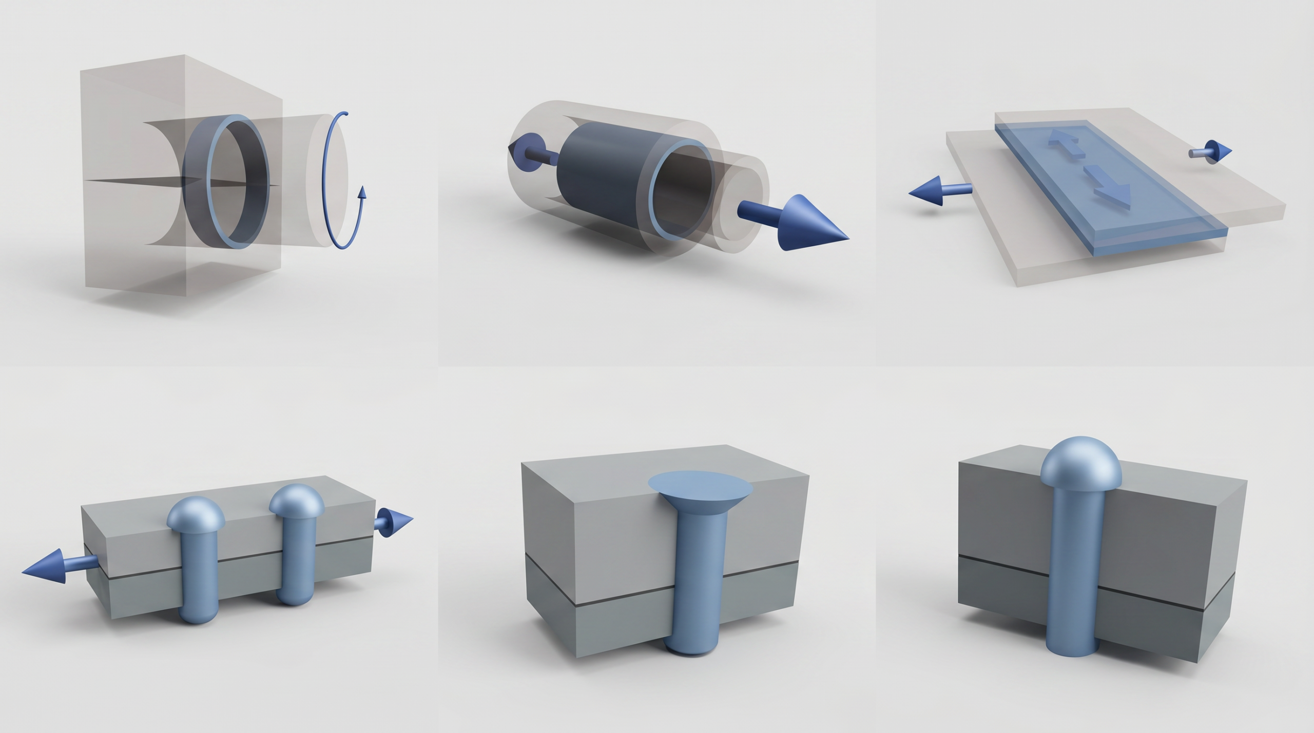
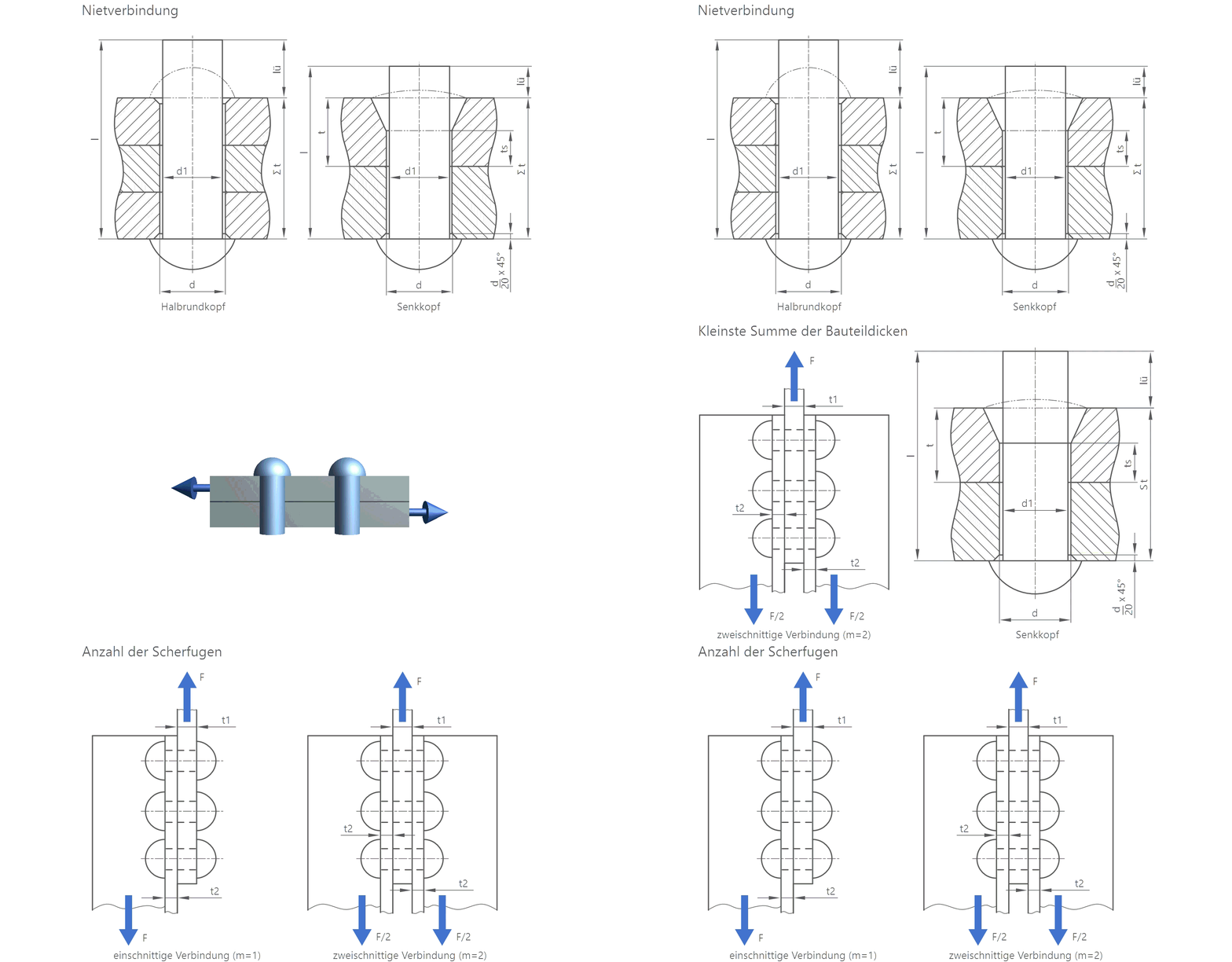
For riveted and bolted connections (soldering joints), different dimensions are key depending on the design. While for riveted connections (riveted joints), factors such as rivet diameter, rivet length, number of rivets, and hole clearance are crucial, soldering joints are evaluated based on normal, shear, and torsional stresses. MDESIGN organizes these calculations in a structured manner and shows which dimensions are required and how much stress the connection is actually subjected to.

Take into account the material properties appropriate for the joint
The load-bearing capacity of a riveted or brazed joint depends directly on the materials used and their allowable properties. MDESIGN provides a comprehensive materials database containing relevant properties for various fasteners and material groups.
Factors taken into account include shear strengths from soldering joints, allowable shear stresses, hole wall pressures, and rivet materials. In addition, users can add their own materials, internal parameters, and company-specific material data, save them, and use them consistently for recurring calculations.
This allows standard materials and company-specific specifications to be mapped in a shared database, and connections to be evaluated more closely in line with the actual design.
Use the results for further design
MDESIGN systematically compiles the relevant stresses, load-bearing capacities, and required dimensions. This not only makes it possible to verify whether a connection is adequately dimensioned, but also to identify which parameter determines the design.
Design engineers can use this information to make specific decisions: adjust the number of rivets, change the diameter, increase the soldering area, or choose a different type of joint. This makes it easier to compare different variants and allows for more targeted design changes.
01
Automatically generated charts
All relevant results are presented clearly. Rivet load-bearing capacity, required number of rivets, hole wall pressure, and solder joint stresses indicate the limits that apply to each joint and where adjustments may be necessary.
|
02
Intuitive user interface
A clearly organized interface, intuitive input options, help texts, and predefined calculation formulas simplify the processing of various riveting and soldering joints. With aiven, an AI assistant is also available directly within the workflow—which is particularly helpful when specific calculation scenarios occur only rarely.
|
Documentation and proof at the touch of a button
Automatically generate technical documentation.
All input data, standards, boundary conditions, results, and graphics are automatically compiled into a complete set of documentation. This results in transparent verification documentation for internal development, customers, testing organizations, or manufacture.
Features of the MDESIGN riveting and soldering joints
The calculation methods are organized by Soldering joints, rivet dimensions, and rivet design verifications. Inputs and results are compared only within the actual calculation steps.
-
Basis for calculation
The modules support the design and verification of typical connections in mechanical engineering, steel construction, and crane manufacturing.
- Calculation based on the literature
- Design and Verification
- Consideration of Geometry, Loading, and Material
- Comparison of Existing and Allowable Loads
- Assessment of Joint Strength
-
Soldering joints
The various Soldering joints s are calculated separately based on their geometry and the type of load they are subjected to.
Butt joint
Evidence of a solder joint subjected to tensile stress.
Input values
- Solder joint width
- Solder joint thickness
- Rated Force
- Application factor
- Tensile Strength of the Solder Joint
- Required Security
Calculated Results
- Existing normal stress
- Permissible Normal Stress
- Evaluation of the Strength Analysis
Overlap Joint
Evidence of a solder joint subjected to shear stress over its entire surface.
Input values
- Solder joint width
- Overlap Length
- Rated Force
- Application factor
- Shear Strength of the Solder Joint
- Required Security
Calculated Results
- Existing shear stress
- Permissible shear stress
- Evaluation of the Strength Analysis
Tube-to-Solid Bar Plug-in Connection
Verification under shear force or torsional moment.
Input values
- Diameter of the brazing ring
- Overlap Length
- Rated Force or Rated Torque
- Application factor
- Shear Strength of the Solder Joint
- Required Security
Calculated Results
- Existing shear or torsional stress
- Permissible shear or torsional stress
- Evaluation of the Strength Analysis
-
Rivet dimensions
The geometric design depends on the component thickness, clamping length, and rivet type.
Rivet hole and raw rivet diameter
Determining the required diameters based on the thinnest component thickness.
Input values
- Minimum component thickness
Calculated Results
- Rivet hole diameter
- Raw pipe diameter
Rivet length
Determining the required rivet length, including the projection.
Input values
- Clamping length
- Raw pipe diameter
- Type of Lock Cylinder
- Hand or machine riveting
Calculated Results
- Required Overhang
- Required rivet length
-
Riveting capacity & number of rivets
The strength evaluation and sizing of the rivet group are combined into a single calculation area.
Load-bearing capacity analysis
Evaluation of an existing riveted joint.
Input values
- Force acting on the joint
- Number of load-bearing rivets
- Number of shear joints
- Rivet hole diameter
- Minimum component thickness
- Minimum sum of component thicknesses
- Permissible shear stress
- Permissible hole pressure
Calculated Results
- Existing shear stress
- Existing hole jamb pressure
- Comparison with the permissible values
- Evaluation of the Strength Analysis
Required Number of Rivets
Sizing the rivet group based on the applicable load.
Input values
- Dominant Load Type
- Force acting on the joint
- Number of shear joints
- Rivet hole diameter
- Minimum component thickness
- Permissible shear stress
- Permissible hole pressure
Calculated Results
- Minimum number of rivets due to shearing
- Minimum number of rivets based on the hole diameter
- Required Number of Rivets
-
Materials & properties
For each individual verification, the relevant material properties and limit values are used.
- Tensile Strength of the Solder Joint
- Shear Strength of the Solder Joint
- Riveting material
- Component Material
- Permissible shear stress
- Permissible hole pressure
- Material-Dependent Threshold Values
-
Results & analyses
The calculation provides a concise summary of the results relevant to the technical evaluation.
- Rivet hole and raw rivet diameter
- Rivet length and overhang
- Minimum number of rivets required
- Existing and Permissible Shear Stress
- Existing and Permissible Hole Jamb Pressure
- Existing and Permissible Normal Stress
- Existing and permissible shear or torsional stress
- Unambiguous Evaluation of the Strength Analysis
Try it for free – Your access to MDESIGN
Discover for free
Learn about the features
Just get started
No download, no installation
Full range of services
14 days of access to all sections