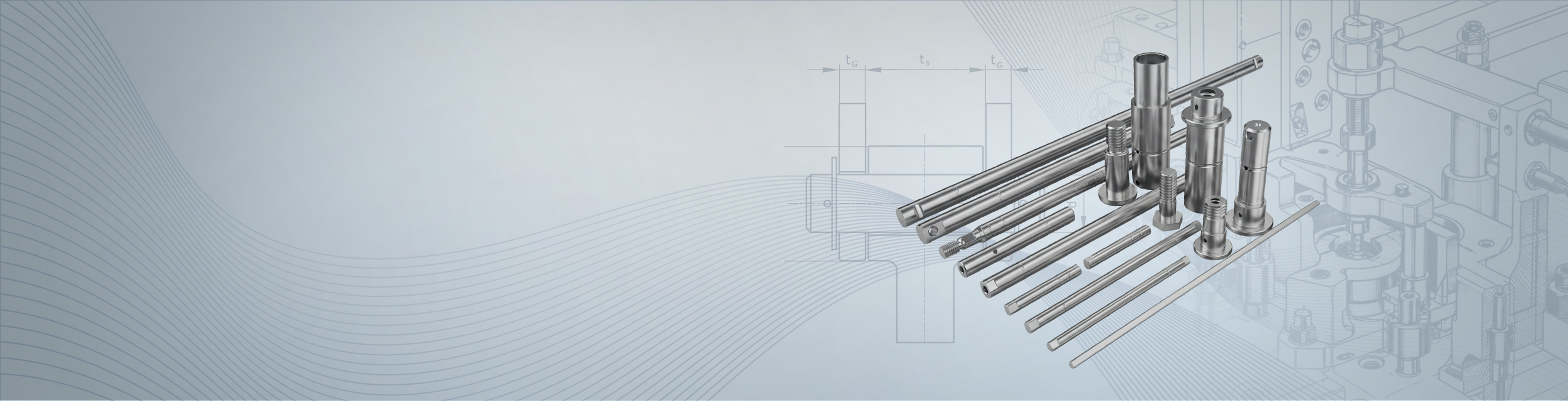
Bolts and pins: Calculation for
greater technical confidence
Determine Load Capacity and Dimensions Correctly from the Start
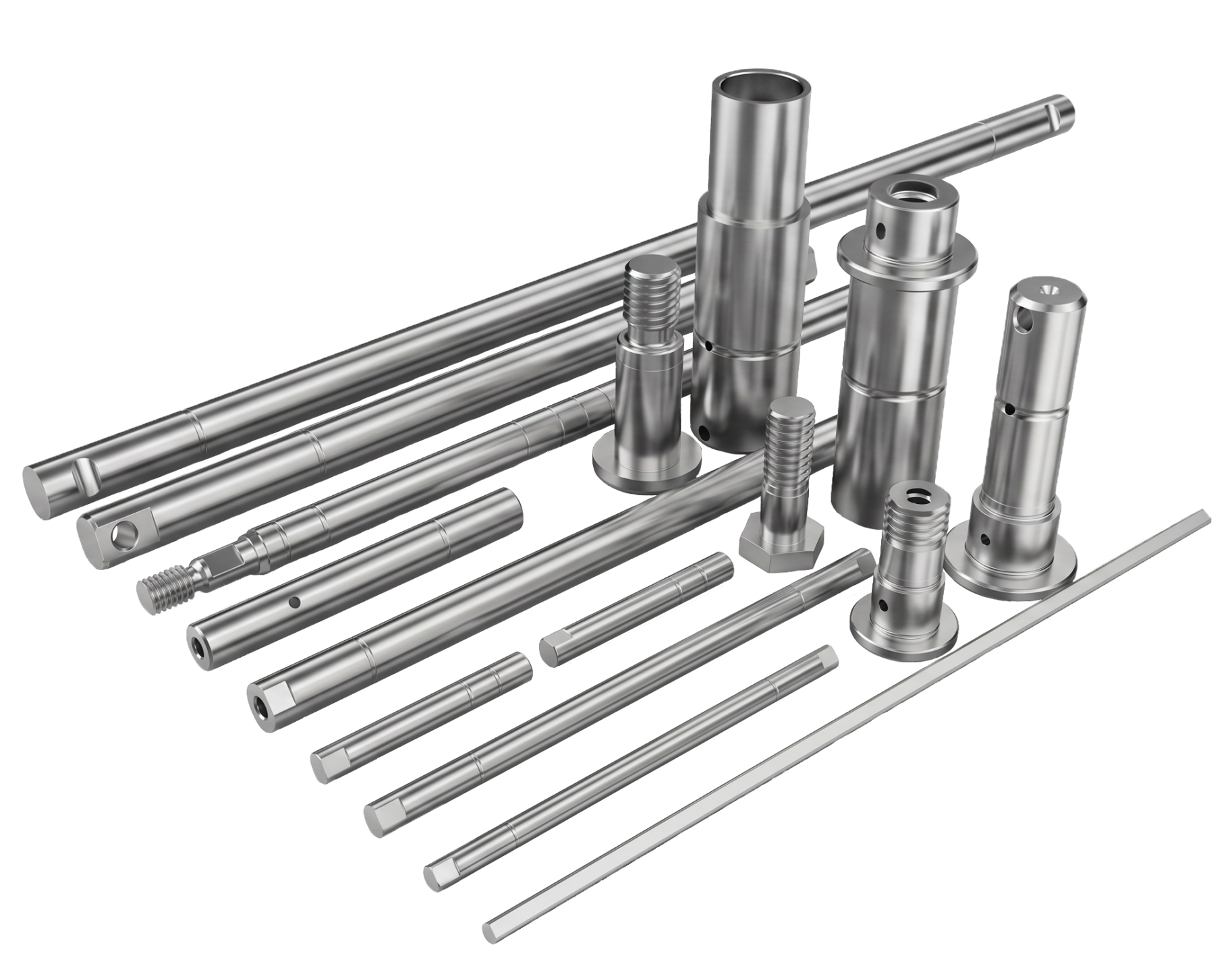
Bolts and pins transmit forces, guide components, and secure moving joints. It is crucial that the diameter, installation conditions, material, and load are properly matched.
MDESIGN It calculates bending, shear, and surface stress and uses these values to determine, among other things, required dimensions, allowable forces, and safety factors. This allows for the precise sizing of connections and the early identification of design margins.
Standards and Guidelines for Bolts Taken into Account
Headless bolts
DIN EN 22340
Bolt with a head
DIN EN 22341
Bolt with threaded shank
DIN 1445
Establish Standards, accelerate Engineering
MDESIGN provides a consistent basis for calculations across the entire team. Structured data entry, centrally maintained calculation bases, and consistent documentation ensure that results remain traceable and comparable across projects.
For over 40 years, MDESIGN has been helping companies calculate and design technical components—today with more than 35,000 users worldwide.
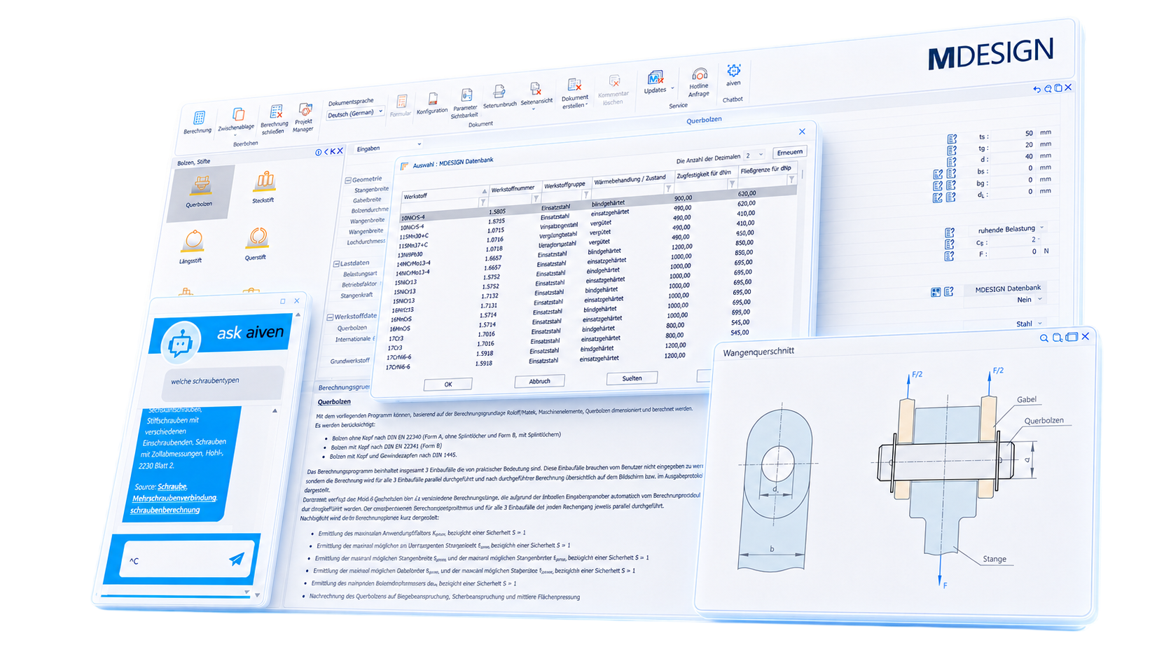
Combining Forces, Stresses, and Dimensions
In bolt and pin connections, multiple stresses often act simultaneously. Bending, shear, and normal stress collectively determine the dimensions required for the connection. MDESIGN combines geometry, loads, material properties, and safety requirements into a single calculation. In addition to existing stresses, the software can determine, among other things, minimum bolt or pin diameters, required widths and lengths, and maximum transferable forces. This not only provides designers with verification for an existing geometry but also allows them to derive appropriate dimensions directly from the load case. Variants can be evaluated more quickly, design iteration cycles can be shortened, and design decisions can be made earlier.
Use Material Data Directly for Real- Design
The load-bearing capacity of a bolt or pin connection does not depend solely on its geometry. Material strength and allowable stresses are key factors in determining which forces can be transmitted.
MDESIGN provides a comprehensive materials database with relevant properties for this purpose. In addition, users can add their own materials, internal properties, and company-specific material data and save them for recurring calculations.
This allows standard materials and company-specific specifications to be used in a shared database. This eliminates the need for manual data maintenance, reduces data entry errors, and ensures that teams work from the same technical foundation when performing recurring tasks.
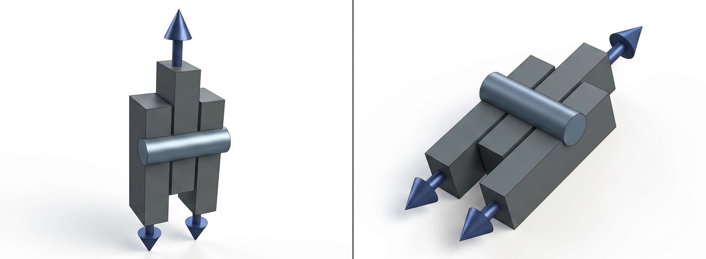
Understanding Results and Purposefully Building on Connections
MDESIGN It presents stresses, surface pressures, safety factors, required diameters, and allowable forces in a structured manner. This quickly reveals which load determines the joint’s behavior and where design margins exist.
Direct actions can be derived from these results: adjusting diameters, changing lever arms, optimizing component widths, switching materials, or exploring alternative connection methods.
This turns the calculation into a concrete decision-making tool. Design engineers can rule out options more quickly, reduce unnecessary iterations, and arrive at a technically sound solution more quickly.

01
Automatically Generated Statement
Displays stresses, safety factors, and surface stresses directly within the results overview. Instead of changing multiple parameters at once, the " Design " can be optimized specifically where action is actually needed.
|
02
Intuitive User Interface
The clearly organized interface, intuitive input options, help features, and built-in fundamentals make it easy to get started. AI assistance provides designers with support throughout the work process. This also simplifies calculations that aren't performed on a daily basis.
|
Documentation and proof at the touch of a button
Automatically generate technical documentation.
All input data, standards, boundary conditions, results, and graphics are automatically compiled into a complete set of documentation. This results in transparent verification documentation for internal development, customers, testing organizations, or Manufacture.
MDESIGN 's Bolt and Pin Calculation Features
The calculation methods are categorized by cross bolts, transverse, longitudinal, and dowel pins, as well as general shear stress. Input data and results are compared only within the actual calculation steps.
-
Basis for Calculation
The modules support design and verification under static, gradually increasing, and varying loads.
- DIN EN 22340 for headless bolts
- DIN EN 22341 for bolts with heads
- DIN 1445 for bolts with heads and threaded studs
- Calculation Based on the Literature
- Static and dynamic loads
- Material Properties Affected by Temperature and Size
-
Cross pin
Three practical installation scenarios are evaluated simultaneously for bending, shear, normal stress, and flange stress.
Check the connection
Verification of an existing cross bolt for all installation scenarios.
Input values
- Bar and Fork Width
- Bolt and Hole Diameters
- Jaw widths of the bar and fork
- Rod force
- Load Type and Application Factor
- Materials Used for Bolts, Forks, and Rods
Calculated Results
- Bending Moment per Installation Case
- Bending and Shear Stress
- Surface compression in the rod and fork
- Safeties against bending, shear, and compressive stress
- Normal stresses and Safeties s of the flange cross-sections
Size the connection
Identification of missing geometric or load parameters.
Input values
- Existing Geometry
- Member force or application factor
- Type of Load
- Material Properties
Calculated Results
- Maximum application factor
- Maximum Transmissible Rod Force
- Minimum and maximum bar width
- Minimum and maximum fork width
- Minimum bolt diameter
-
Cross Pin
Analysis of normal stresses in the Shaft , and hub, as well as the shear stress in the pin.
Check the connection
Verification of an existing cross-pin connection.
Input values
- Pen diameter
- Shaft diameter
- Hub Wall Thickness
- Rated torque
- Load Type and Application Factor
- Pin Type and Notched Pin Factor
- Materials used for the pin, Shaft , and hub
Calculated Results
- Surface pressure in hub and shaft bores
- Shear stress in the cross pin
- Permissible Surface Pressures and Shear Stress
- Safeties for hub, Shaft , and pin
Size the connection
Determination of required dimensions and load limits.
Input values
- Existing Geometry
- Rated torque or application factor
- Type of Load
- Material Properties
Calculated Results
- Maximum application factor
- Minimum pen diameter
- Minimum shaft diameter
- Maximum transmissible torque
- Minimum hub wall thickness
-
Long Pin
Longitudinal pins are evaluated based on the average surface pressure between the pin, Shaft , and the hub.
Input values
- Pen diameter
- Shaft diameter
- Supporting pin length
- Rated torque
- Load Type and Application Factor
- Notch factor
- Materials used for the pin, Shaft , and hub
Calculated Results
- Existing average surface pressure
- Permissible average surface pressure
- Safety Against Surface Pressure
- Effective tensile strengths of the materials involved
-
Plug pin
Analysis of bending and shear stress caused by shear force and bending moment.
Check the connection
Recalculation of an existing plug-in pin.
Input values
- Pen diameter
- Lever Arm of the Bending Force
- Insertion depth
- Bending force
- Load Type and Application Factor
- Notch factor
- Materials of the pin and component
Calculated Results
- Total length of the plug pin
- Bending Moment and Bending Stress
- Shear Stress and Bending Moment on a Plate
- Maximum average surface pressure
- Safeties against bending and surface compression
Size the connection
Determination of the required geometry and permissible load.
Input values
- Existing Geometry
- Bending force or application factor
- Type of Load
- Material Properties
Calculated Results
- Maximum Allowable Bending Force
- Maximum application factor
- Minimum pen diameter
- Maximum Permissible Lever Arm
- Minimum insertion depth
-
Shear stress
The auxiliary module determines the existing shear stress and the allowable shear stress using two calculation methods.
Existing shear stress
Calculation based on shear force and effective cross-sectional area.
Input values
- Shear force
- Cross-sectional area
- Number of cross-sectional areas or cross-sectionality
Calculated Results
- Existing shear stress
Permissible shear stress
Determination of the threshold value using two possible methods.
Input values
- Shear Strength and Safety Factor
- Or allowable shear force, cross-sectional area, and slenderness ratio
Calculated Results
- Permissible shear stress according to Diagram 1
- Permissible shear stress according to Diagram 2
-
Materials & Properties
The strength evaluation takes into account the materials involved and their effective properties.
- Material selection from the " MDESIGN" database
- Tensile Strength
- Yield Strength and Elastic Limit
- Temperature-Dependent Material Properties
- Effect of Component Size
- Edge Hardening
- Anisotropy or rolling direction
- Notch Pin Factors
- Permissible Bending and Shear Stresses
- Permissible surface pressures
-
Results & Analyses
The key results are summarized by connection type.
- Bending, Shear, and Normal Stresses
- Surface stresses in pin, Shafts, hub, fork, and rod areas
- Safeties against bending, shear, and compressive stress
- Minimum required bolt and pin diameters
- Minimum required Shafts and hub dimensions
- Maximum Transmissible Forces and Torques
- Maximum Allowable Application Factor
- Permissible lever arms and required insertion depths
- Comparison of Existing and Permissible Values
Try it for free – Your access to MDESIGN
Discover for free
Learn about the features
Just get started
No download, no installation
Full Range of services
14 days of access to all sections