Flange calculation
for greater certainty
behind every decision
Preparing Flange Connections for Real-World Operating Conditions
In flange connections, many factors interact directly with one another: flange geometry, bolt preload, gaskets, materials, pressure, and temperature all work together to determine how reliably the connection performs during operation.
MDESIGN It considers these parameters as an integrated system and combines leak-tightness and strength analyses in a single calculation in accordance with DIN EN 1591-1 and AD 2000. This illustrates how assembly, operation, and testing affect bolt forces, sealing forces, and surface pressures.
This simplifies the design process, reduces unnecessary iterations, and provides earlier clarity on whether the connection meets the required operating conditions.
Standards and regulations taken into account for Flange and pressure equipment
Flange Design
DIN EN 1591
Pressure Equipment
A.D. 2000
Establish Standards, Accelerate Engineering
MDESIGN provides a consistent basis for calculations across the entire team. Structured data entry, centrally maintained calculation bases, and consistent documentation ensure that results remain traceable and comparable across projects.
For over 40 years, MDESIGN has been helping companies calculate and design technical components—today with more than 35,000 users worldwide.

Leak-Tightness and Strength Verification in a Single Model
A flange connection is properly designed only when not only the strength is adequate, but also the gasket remains sufficiently loaded under all relevant conditions. MDESIGN calculates, among other things, assembly preload forces, bolt forces, gasket forces, gasket surface pressures, tightening torques, leakage rates, and safety factors. Assembly, operating, and test conditions are all taken into account. This makes it possible to identify which condition determines the joint’s performance and whether changes to preload, the seal, or the geometry are necessary. Design engineers can dimension components more precisely and avoid optimizing tightness and strength independently of one another.
Select flange gaskets directly from the database
MDESIGN contains flange gaskets from various manufacturers with stored specifications for pressure, temperature, shape, thickness, and material type. The appropriate data set can be incorporated into the calculation or supplemented with your own Sealing . This eliminates the need for manual data searches, reduces data entry errors, and makes it easier to compare different Sealing directly within the specific flange system.
Pressure, temperature, shape, thickness, and material type.
Select and use directly for the flange calculation.
Add gasket data records and use them for calculations.
Monitoring Pressure, Temperature, and Fluid in Actual Operation
Flange connections change during operation. Internal pressure, test pressure, varying temperatures of the flange, bolts, and gasket, as well as additional forces and torques, all act on the system simultaneously.
MDESIGN takes these conditions directly into account in the calculation. When performing calculations according to AD 2000, various operating media—such as liquids, gases, or steam—can also be included.
This makes it possible not only to assess the assembly condition, but also to monitor how sealing force, screw stress, and leakage rates change under real operating and test conditions.

Use the results to specifically improve leak tightness and design
01
Evaluate Tightness and Strength
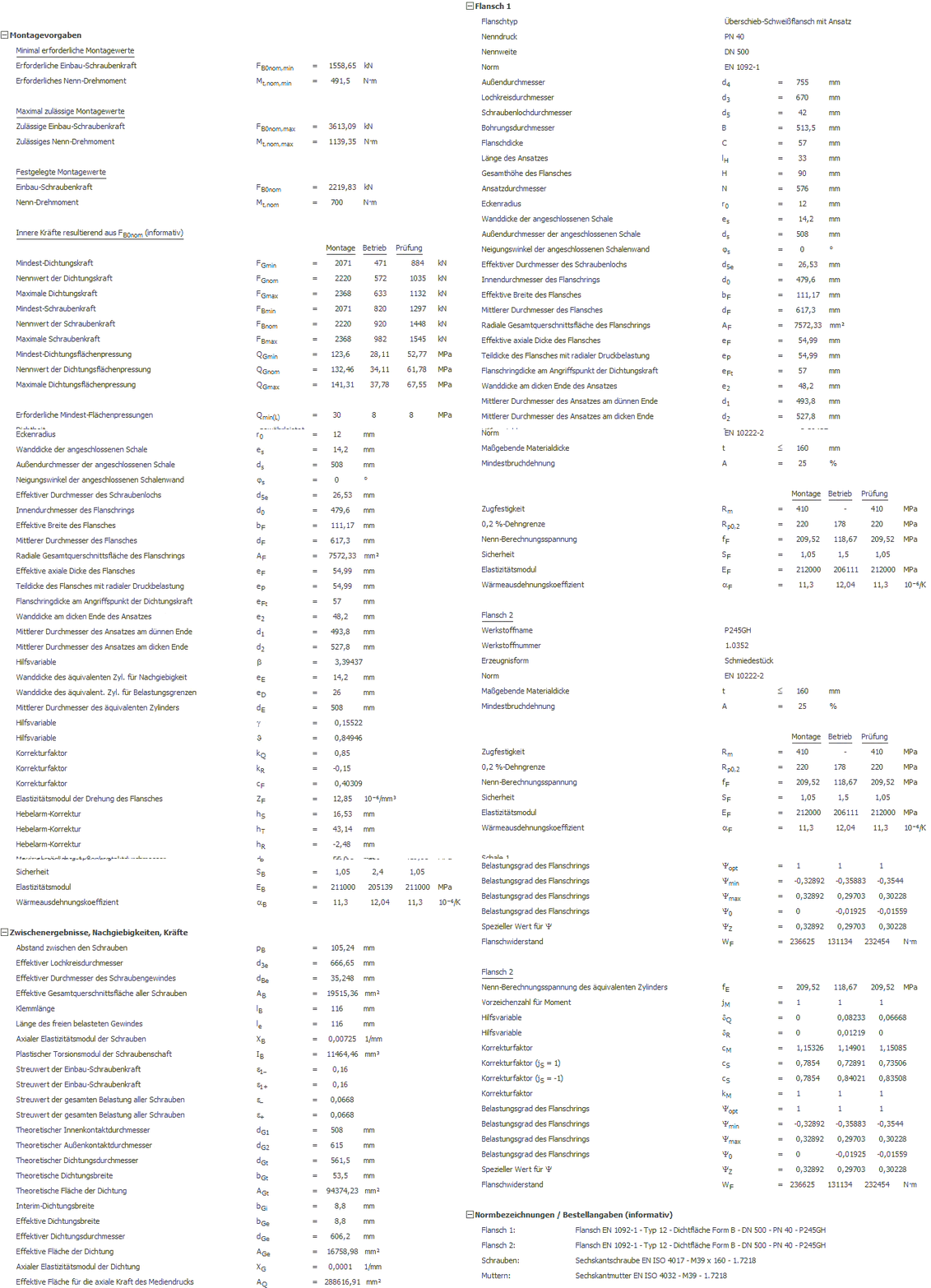
Tables and graphs show how assembly, operating, and test conditions affect seals, bolts, and flanges. This makes it quickly clear which load case is critical and where design measures should be taken.
|

02
Intuitive 3D Modeling
The flange type, bolts, gasket, and loads can be configured in the 3D model. This makes it easier to understand the assembly and interaction of the individual components and to clearly compare different variants.
|
Documentation and proof at the touch of a button
Automatically generate technical documentation.
All input data, standards, boundary conditions, results, and graphics are automatically compiled into a complete set of documentation. This results in transparent verification documentation for internal development, customers, testing organizations, or Manufacture.
STEP Export Directly from the Calculation
Components are modeled, analyzed, and evaluated in MDESIGN . The validated results can then be exported directly as STEP files and transferred to CAD systems. This ensures that the entire development process remains consistent—without any data discontinuities or the need for manual geometry transfer.




Features of the MDESIGN Flange Calculation Tool
Flange connections in accordance with EN 1591 and flange connections in accordance with AD 2000.
-
Basis for Calculation
- DIN EN 1591-1
- AD 2000 Information Sheet B 0
- AD 2000 Information Sheet B 7
- AD 2000 Information Sheet B 8
- DIN V 2505
- Directive 2014/68/EU
-
Flange Connections in Accordance with EN 1591
Input values
Boundary conditions, load data, geometry, seals, bolted connections, and material data.
Input values
- Specifying Installation Values
- Specified installation torque
- Specified Rated Torque
- Media Pressure
- Temperature at Flange 1
- Temperature at Flange 2
- Temperature Screws
- Temperature of the Panes
- Temperature Seal
- External Axial Load
- Resulting external additional bending moment
- Resulting shear force
- External Additional Torsional Moment
Output values
- Required installation torque
- Required Rated Torque
- Permissible Installation Screw Force
- Permissible Rated Torque
- Minimum screw torque
- Rated screw force
- Maximum screw force
- Minimum sealing force
- Rated sealing force
- Maximum sealing force
- Minimum Sealing Surface Pressure
- Rated value of the sealing surface pressure
- Maximum Sealing Surface Pressure
Overview of Stress Conditions
Installation, Operation, Testing.
Input values
- Assembly
- Operation
- Exam
- Creeper relaxation factor
- Standard deviation of the installation screw force
- Coefficient of friction in the thread
- Coefficient of friction at the contact surfaces
Output values
- Load rating for screws
- Load rating for seal
- Load rating for flange 1
- Load rating for flange 2
- Leak-proof guaranteed
- Strength Guaranteed
-
Flange Connections According to AD 2000
Input values
Boundary conditions, load data, geometry, gasket, bolts, and flange material.
Input values
- Verification Procedures
- Working fluid
- Specifying Installation Values
- Utilization of the yield point during tightening
- Pipe Additional Force
- Additional bending moment in the pipe
- Internal pressure
- Operating temperature
- Internal Test Pressure
- Test temperature
- Flange Type
- Rated pressure
- Nominal diameter
Output values
- Sealing force
- Minimum screw torque
- Required Shaft Diameter
- Required Thread Core Diameter
- Flange force
- Internal Pipe Pressure Force
- Pipe Additional Force
- Existing Voltage Installation
- Existing Voltage - Operation
- Existing Voltage Test
- Safety factor for flanges
- Safety factor for screws
- Safety factor against leakage
Output values
Flange calculation in accordance with AD 2000 Information Sheet B 8.
Input values
- Flange Dimensions
- Seal parameter
- Screw Designation
- Strength Class
- Flange material
Output values
- Required height of the flange plate
- Required Minimum Pipe Wall Thickness
- Required Shaft Diameter
- Required Thread Core Diameter
- Tightening torque
- Permissible Voltage for Installation
- Permissible Operating Voltage
- Permissible Voltage Test
-
Flange Type
- Integrated Flange
- Weld-on flange
- Weld-on flange
- Slip-on Weld Flange with Lobe
- Integral flange with cylindrical extension
- Integral flange with a tapered extension
- Blind flange
- Flange s with a waistband or hem
- Loose flange with a smooth collar
- Loose flange with a flared pipe end
- Loose flange with a welded-on ring
- Loose flange with press-fit flange
- Loose flange with a welded collar
-
Screw connection
- Type of Screw Connection
- Alignment of the screws
- Screw type
- Screw Designation
- Screw length
- Number of screws
- Nominal diameter
- Drawing Process
- Number of assembly and tightening operations
- Coefficient of friction in the thread
- Coefficient of friction at the contact surfaces
- Strength Class
- Nuts
- Washer / Expansion Sleeve
-
Seal
- Seal Designation
- Seal Manufacturer
- Material
- Seal Type
- Seal shape
- Seal Thickness
- Outer diameter
- Inner diameter
- Leakage Class
- Coefficient of friction between the gasket and the flange sealing surface
- Minimum surface pressure required during installation
- Minimum surface pressure required during operation
- Maximum allowable contact pressure on sealing surfaces
- Modulus of elasticity
- Creeper relaxation factor
-
Material Data
- Material Name
- Material Number
- Product Form
- Standard
- Minimum elongation at break
- Tensile Strength
- 0.2% yield strength
- 1.0% yield point
- Rated Calculation Voltage
- Safeties
- Modulus of elasticity
- Coefficient of thermal expansion
- Determination of design stresses according to
-
Results
- Minimum required installation values
- Maximum Permissible Installation Values
- Specified installation values
- Internal forces resulting from FB0nom
- Screw force
- Sealing force
- Sealing Surface Pressure
- Load rating for screws
- Load rating for seal
- Load Rating for Flange
- Leak-proof guaranteed
- Strength Guaranteed
- Notes
Try it for free – Your access to MDESIGN
Discover for free
Learn about the features
Just get started
No download, no installation
Full Range of services
14 days of access to all sections