
FEM results according to FKM
reliably demonstrate
Convert existing stresses from FEM, calculations, or measurements directly into FKM analyses that can be used in
.
Stress is converted into a verifiable strength analysis
With the MDESIGN component strength verification according to FKM, you can check whether existing stresses derived from FEM, calculations, or measurements meet the required safety criteria. The module supports the computational strength verification in accordance with the FKM guideline for mechanical components.
This feature is particularly powerful following an FE analysis: principal stresses, normal forces, stress amplitudes, or local stresses are imported, combined with material properties according to FKM, and documented as load capacity, safety, and verification reports.
Establish standards, accelerate engineering
MDESIGN provides a consistent basis for calculations across the entire team. Structured data entry, centrally maintained calculation bases, and consistent documentation ensure that results remain traceable and comparable across projects.
For over 40 years, MDESIGN has been helping companies calculate and design technical components—today with more than 35,000 users worldwide.
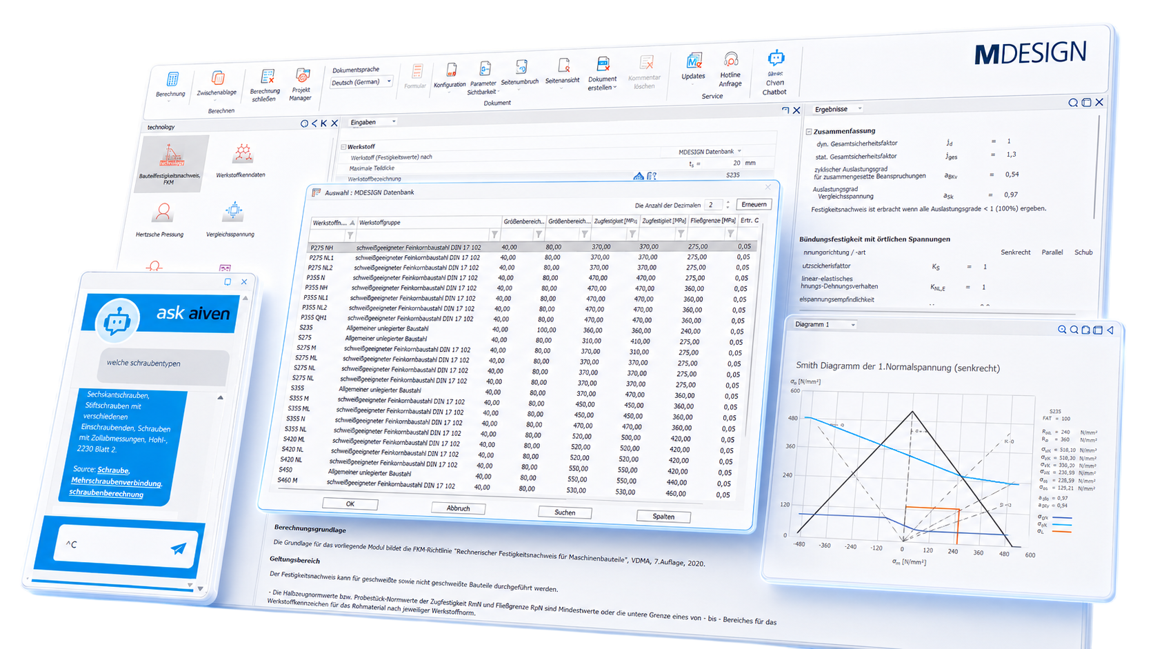
Direct evidence of existing tensions
MDESIGN strength assessment supplements FEM and traditional calculations with a standard-based safety verification according to FKM.
Evaluate FE stresses
Existing local stresses obtained from FEA calculations, measurements, or analytical approaches can be used for verification.
Perform static and dynamic analysis
The module supports static strength analyses as well as fatigue, durability, and serviceability analyses.
Safety instead of guesswork
Load factors, safety factors, and diagrams clearly show whether the design verification has been met or whether critical areas need to be revised.
Material data according to FKM
Integrated material properties for steel, castings, and aluminum reduce manual data maintenance and improve traceability.
For static strength and fatigue strength
The FKM guideline describes static and fatigue strength analyses. For fatigue analysis, depending on the load characteristics, endurance, time, or service life strength analyses are possible.
MDESIGN summarizes the relevant input data and results in a structured manner: stresses, material data, temperature factors, safety factors, support factors, roughness factors, effects of mean stress, and utilization rates.
Structural analysis
Verification of the existing equivalent stress against the permissible strength assessment, including safety factors.
Dynamic verification
Evaluation of cyclic loading, stress amplitudes, medium-voltage effects, and number of load cycles.
Local stresses
Analysis of stresses at the verification point, for example, based on FEM results or measurement data.
Select material properties with confidence and use them directly for FKM verification
MDESIGN technology accesses structured material data, including strength values, material groups, size ranges, and characteristic values. In addition to integrated data, users can also use their own materials from the company database or their own specifications entirely.
Use safety factors and utilization levels to support decisions
|
01
Create strength verification step by step
The MDESIGN interface supports the quick definition of all relevant boundary conditions and verification parameters.
Libraries and help systems facilitate the reliable creation of strength verifications that comply with standards.
|
02
Assessing the reliability of evidence in the Haigh diagram
The results of the strength analysis are clearly visualized in the Haigh diagram. This allows safety margins, stress ratios, and critical load conditions to be quickly identified and evaluated.
|
The most important results are automatically evaluated
MDESIGN calculates the relevant design parameters in accordance with the FKM guideline and makes them available directly for technical evaluation.
Documentation and proof at the touch of a button
Automatically generate technical documentation.
All input data, standards, boundary conditions, results, and graphics are automatically compiled into a complete set of documentation. This results in transparent verification documentation for internal development, customers, testing organizations, or manufacture.
Features of the MDESIGN component strength analysis according to FKM
The functions are organized by stress analysis, component type, materials, influencing factors, and static and dynamic strength evaluation .
-
Verification using local stresses
Input values
- Principal stresses
- Standard voltages
- Shear stresses
- Stresses at the verification point
- Tensions at the base
- Distance to the base
- Tension
- Medium voltage
- Breakdown voltage
- Reference voltage
- Number of load cycles
Output values
- Reference voltage
- Hydrostatic stress
- Degree of multi-axiality
- Static utilization factor
- Cyclical capacity utilization rate
- Overall safety factor
- Comparative safety, fatigue strength
- Compressive strength vs. tensile strength
- Comparison of strength against yield strength
Sample results chart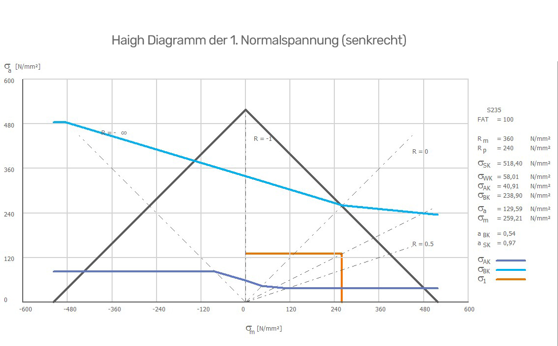
An example of a graphical analysis of the first normal stress. -
Non-welded components
Input values
- Material
- Component shape
- Effective diameter
- Temperature
- Surface roughness
- Edge hardening
- Protective coating
- Stress perpendicular to the rolling direction
- Plastic form number
- Method of calculating the support figure
Output values
- Tensile strength of components
- Component yield strength
- Technological size influence factor
- Anisotropy factor
- Roughness factor
- Notch factor
- Mechanical strength index
- Kt-Kf ratio
- Static strength assessment
- Cyclic load wheel
- Static load wheel
-
Welded components
Input values
- Type of stress to be detected
- Structural stresses
- Notch stresses
- Seam type
- Type of welded connnections
- Consistency
- Seam quality
- FAT component class
- Sheet thickness
- Internal stresses
- Heat-affected zone
- Dissociation factor
Output values
- Weld seam factor
- Thickness factor
- Intrinsic stress factor
- Component interchangeability
- Allowable fatigue limit amplitude
- Allowable amplitude for fatigue strength
- Static strength assessment
- Cyclical capacity utilization rate
- Static utilization factor
-
Materials & material properties
- General-purpose unalloyed structural steel
- Fine-grained structural steel suitable for welding
- Quenched and tempered steel
- Tool steel
- Nitriding steel
- Stainless steel
- Cast steel
- Ductile iron
- Cast iron with lamellar graphite
- Molded cast iron
- Worked aluminum alloy
- Cast aluminum material
- Proprietary materials
-
Effects of materials and temperature
Input values
- Standard tensile strength
- Standard yield strength
- Elongation at break
- Standard dimension
- Component dimensions
- Temperature
- Service life at temperature
- Heat-treated condition
Output values
- Effective diameter
- Technological scale factor
- Anisotropy factor
- Temperature factor
- Tensile strength of components
- Component yield strength
- Component heat resistance
- Component hot elongation limit
- Component creep strength
- 1 % Time-Strain limit of the component
-
Static strength assessment
Input values
- Load assumptions
- Consequences of damage
- Probability of occurrence
- Cast quality
- Plastic form number
- Reference voltage
- Hydrostatic stress
Output values
- Overall safety factor
- Total allowable elongation
- Kt-Kf ratio
- Static strength assessment
- Utilization rate of the reference voltage
- Compressive strength vs. tensile strength
- Comparison of strength against yield strength
-
Fatigue strength assessment
Input values
- Number of load cycles
- Type of load
- Tension
- Medium voltage
- Breakdown voltage
- Overload Condition
- Inspection
- Consequences of damage
- Voltage drop
- Surface roughness
Output values
- Medium-voltage factor
- Service life factor
- Component interchangeability
- Allowable fatigue limit amplitude
- Allowable amplitude for fatigue strength
- Cyclical capacity utilization rate
- Cyclic utilization factor for combined loads
- Comparative safety, fatigue strength
-
Support effect & surface influences
Input values
- Voltages at the test point
- Tensions at the base
- Distance to the base
- Notch radius
- Component thickness
- Surface roughness
- Protective coating
Output values
- Relative voltage drop
- Support number according to Stieler
- Statistical support figure
- Deformation-mechanical support factor
- Fracture mechanics support number
- Mechanical strength index
- Roughness factor
- Notch factor
- Design factor
Try it for free – Your access to MDESIGN
Discover for free
Learn about the features
Just get started
No download, no installation
Full range of services
14 days of access to all sections