O-ring seal selection for
confident decisions
Select O-rings appropriate for the installation space, compression, and temperature
MDESIGN Supports the design of typical O-ring applications in Hydraulics, pneumatics, and general fluid technology.
The calculation takes into account actual operating conditions as well as worst-case tolerances, thereby supporting a reliable assessment of leak tightness, clamping force, and installation space.
This makes it clear early on whether the O-ring and the installation space fit within the specified limits and what dimensions are required for the specific installation situation.
Standards and Guidelines Considered for O-Rings and Installation Spaces
Dimensions
DIN ISO 3601-1
Installation spaces
ISO 3601-2
Installation Space Calculation
DIN 3771-5
Aviation Grooves
ISO 23748
Establish Standards, accelerate Engineering
MDESIGN provides a consistent basis for calculations across the entire team. Structured data entry, centrally maintained calculation bases, and consistent documentation ensure that results remain traceable and comparable across projects.
For over 40 years, MDESIGN has been helping companies calculate and design technical components—today with more than 35,000 users worldwide.

Greater reliability in the sizing of grooves and O-rings
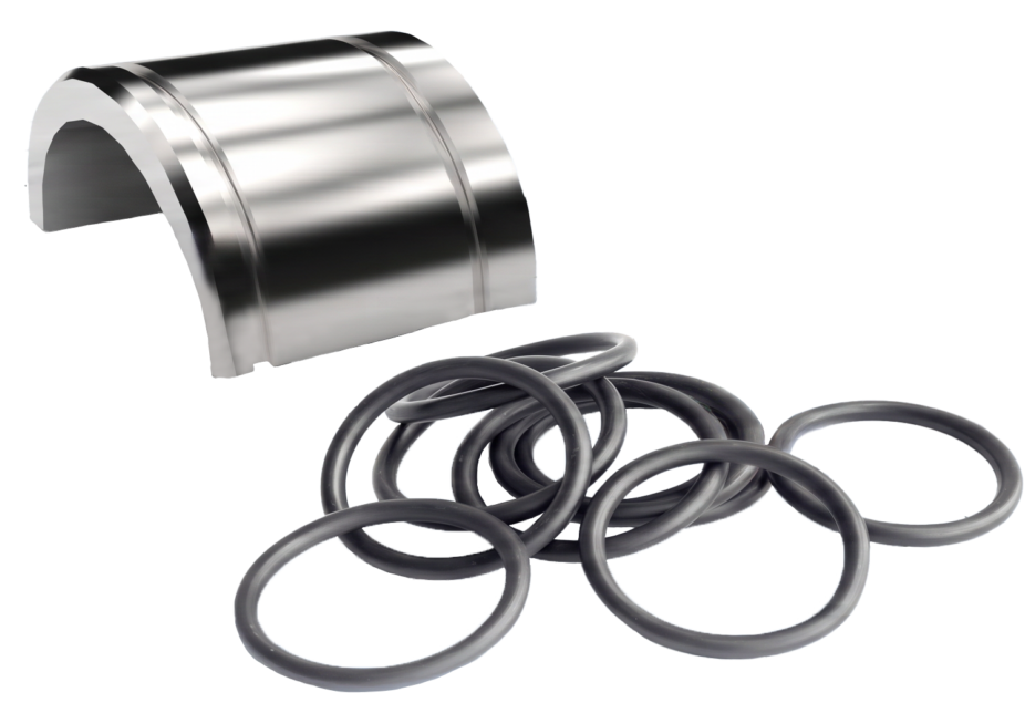
During the design process, the O-ring dimensions and groove geometry must be coordinated. The inner diameter, cord thickness, groove width, groove bottom, installation space height, and circumferential gap all influence the compression, compression ratio, and degree of groove fill. MDESIGN The calculation determines, among other things, the minimum and maximum dimensions of the O-ring and the installation space. Lead-in angles, groove radii, and configurations with one or two support rings can also be taken into account. This allows the O-ring and groove to be evaluated together and different installation scenarios to be compared based on the same calculation principles.
Take temperature, swelling, and expansion into account
O-rings change in size depending on temperature, swelling, and elongation. These changes, in turn, affect the compression, the fit, and the conditions within the installation space.
MDESIGN Takes into account room temperature as well as minimum and maximum operating temperatures. In addition, the coefficient of thermal expansion, swelling, and the reduction in cross-sectional area due to elongation can be factored into the calculation.
This makes it possible to consider different operating conditions as early as the design phase, rather than relying solely on dimensions at room temperature.
Waterproofing Systems
Quickly Understand and Evaluate Results
Among other things, the calculation shows the minimum and maximum compression, compression ratio, groove fill ratio, gap widths, elongation, and compression. This illustrates how tolerances, temperature, and the installation conditions affect the O-ring.
Critical combinations can be identified early on, and O-ring dimensions or installation space can be adjusted accordingly. This reduces unnecessary iterations and provides greater reliability when sizing the groove.
|
01
Guided Input and Results Overview
Structured input forms and wizards provide guidance on O-ring geometry, groove dimensions, temperatures, and tolerances. Different installation scenarios can be clearly documented, and the most important results can then be evaluated in a transparent manner.
|

02
Automatically Generated Charts
The results illustrate compression, groove filling, elongation, and deformation. This makes it easier to understand gap widths and various tolerance scenarios, and to identify critical conditions more quickly.
|
Documentation and proof at the touch of a button
Automatically generate technical documentation.
All input data, standards, boundary conditions, results, and graphics are automatically compiled into a complete set of documentation. This results in transparent verification documentation for internal development, customers, testing organizations, or Manufacture.
Features of the MDESIGN Seal Calculator
The functions are organized in a concise manner by standards, installation scenarios, O-ring dimensions, installation spaces, temperature, compression, and groove fill.
-
Standards & Calculation Bases
- DIN ISO 3601-1
- ISO 3601-2
- DIN 3771-5
- ISO 23748
-
Installation Cases
- Piston seal
- Rod Seal
- Axial Seal
- Externally sealed
- Static
- Dynamic
- Internal seal
- Aviation or aerospace application
- Hydraulic
- Pneumatic
-
O-Ring Dimensions
Input values
- Design
- Load
- Tolerance Class
- Selection Range
- Outer diameter of the groove
- Groove Diameter
Output values
- Inner diameter
- Line thickness
- Outer diameter of the groove
- Groove Diameter
- Shafts-Ø
- Minimum insertion angle of 15 degrees
- Minimum lead angle of 20 degrees
- Groove width without support rings
- Groove width with a support ring
- Groove width with two support rings
- Groove base radius
- Outer Radius of the Groove
- Depth of the installation space
-
O-Ring & Installation Space
Input values
- O-ring inner diameter
- O-Ring Cord Thickness
- Width of the O-ring mounting space
- Width of the O-ring mounting space for axial installation
- Internal Diameter of the Installation Space for Piston Seals
- Bore diameter for piston seal
- Bar diameter
- Outer diameter of the installation space for rod seals
- Outer diameter of the mounting space with axial sealing
- Inner diameter of the mounting space with axial sealing
- Piston diameter
- Bore Diameter for Rod Seals
- Radius at the bottom of the groove
- Height of the installation space
- Upper tolerance
- Lower tolerance
Output values
- Maximum O-ring cord thickness
- Minimum O-ring cord thickness
- Maximum width of the O-ring mounting space
- Minimum width of the O-ring installation space
- Maximum radius at the bottom of the groove
- Minimum radius at the bottom of the groove
- Maximum height of the installation space
- Minimum height of the installation space
-
Temperature, Swelling, and Elongation
Input values
- Room temperature
- Maximum operating temperature
- Minimum operating temperature
- Coefficient of thermal expansion
- Swelling
- Cross-sectional reduction factor during elongation
Output values
- Source factor
- Source diameter
- O-ring diameter
- Maximum Elongation
- Minimal elongation
- Maximum compression
- Minimal compression
- Maximum reduction in cross-sectional area
- Minimal reduction in cross-sectional area
-
Compression & Pressing
Input values
- Desired minimum pressure
- O-Ring Cord Thickness
- Height of the installation space
- Cross-sectional reduction factor during elongation
- Room temperature
- Minimum operating temperature
- Maximum operating temperature
Output values
- Maximum Compression
- Minimum pressure
- Maximum compaction
- Minimal compaction
- O-ring outer diameter when installed
- Inner diameter of the O-ring when installed
- Maximum actual circulating gap
- Minimum actual clearance
- Compression with single-sided contact
- Grouting with a single-sided installation
-
Groove Filling & Gap
Input values
- Width of the O-ring mounting space
- Radius at the bottom of the groove
- O-ring inner diameter
- O-Ring Cord Thickness
- Installation Space Dimensions
Output values
- Maximum groove fill ratio
- Minimum groove fill ratio
- Maximum circumferential gap
- Minimum circumferential gap
- Maximum gap width with centric alignment
- Minimum gap width with centric alignment
- Gap width for single-sided mounting
- Maximum gap for single-sided contact
- Minimum pressure with single-sided contact
Try it for free – Your access to MDESIGN
Discover for free
Learn about the features
Just get started
No download, no installation
Full Range of services
14 days of access to all sections