Multi-bolt calculation for
enhanced safety in bolted joints
Identify the critical screw in the entire set of screws
In multi-bolt connections, an external load is not distributed evenly across all bolts. The geometry, bolt arrangement, stiffness, and force transmission determine which bolt is subjected to the greatest stress.
MDESIGN multibolt calculates this force distribution in accordance with VDI 2230, Part 2, for the entire bolt array. This allows you to identify which bolt is the critical one, how forces and moments are distributed within the joint, and where the Design can be specifically improved.
Establish Standards, accelerate Engineering
MDESIGN provides a consistent basis for calculations across the entire team. Structured data entry, centrally maintained calculation bases, and consistent documentation ensure that results remain traceable and comparable across projects.
For over 40 years, MDESIGN has been helping companies calculate and design technical components—today with more than 35,000 users worldwide.

Calculate force distribution across the entire bolt field
Axial forces, shear forces, bending moments, and torsional moments act on the entire joint, but not equally on every bolt. MDESIGN multibolt therefore calculates the load on each individual bolt in the field, taking into account geometry, bolt positions, plate stiffness, and force application. This reveals how the external load is actually distributed across the joint. Design engineers can identify critical bolts early on, compare different bolt configurations, and adjust the arrangement as needed.
Flexibly model different flange and connection types
Whether it's a circular flange, a rectangular connection, or a complex profile geometry: The shape of the connection directly influences how loads are distributed among the individual bolts.
MDESIGN multibolt allows for different connection types and bolt arrangements directly within the model. This makes it possible to accurately simulate the actual Design and analyze its effect on bolt loads.
Include operating conditions directly in the multi-bolt calculation
Even in multi-bolt connections, preload forces and load conditions do not necessarily remain constant during operation. Temperature changes, different materials, and settlement can alter the force distribution within the bolt array.
MDESIGN takes these boundary conditions directly into account in the calculation. Custom material properties for screws and components, as well as different temperature conditions, can also be entered.
This makes it possible to determine whether the calculated load distribution will remain the same under actual operating conditions and whether, as a result, a different bolt will become the critical point of the joint.

Determine and verify the screw under the highest load
01
Automatically Generated Charts
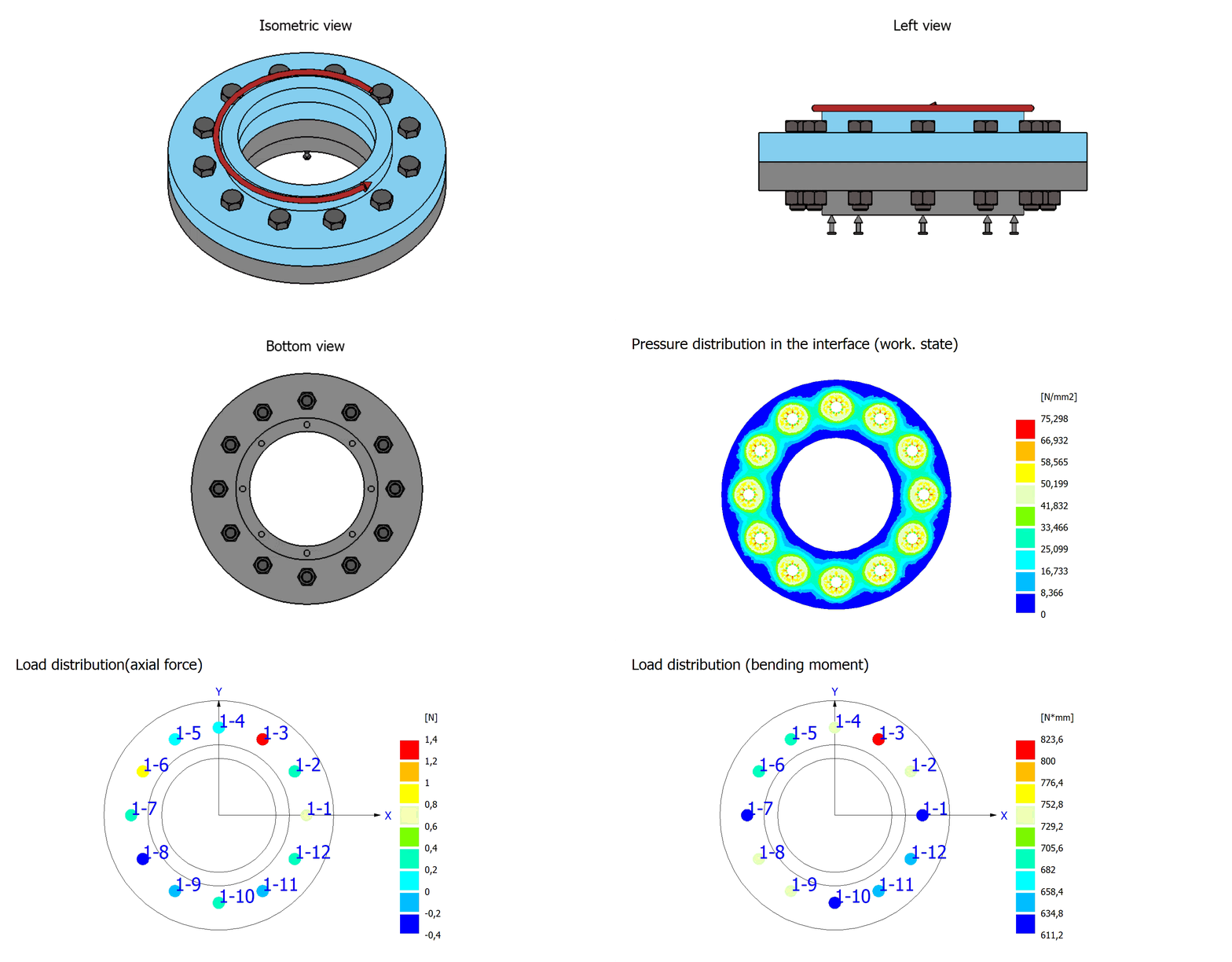
Additional forces acting on the bolts, stress distributions, and loads within the bolt field are clearly visualized. Color scales and heat maps immediately show which areas are under critical stress.
|
02
Intuitive 3D Modeling
The screw arrangement, connection geometry, and load can be adjusted and recalculated in the model. This makes it possible to compare which design variant produces the most favorable load distribution.
|
Documentation and proof at the touch of a button
Automatically generate technical documentation.
All input data, standards, boundary conditions, results, and graphics are automatically compiled into a complete set of documentation. This results in transparent verification documentation for internal development, customers, testing organizations, or manufacture.
STEP Export directly from the Calculation
Components are modeled, analyzed, and evaluated in MDESIGN. The validated results can then be exported directly as STEP files and transferred to CAD systems. This ensures that the entire development process remains consistent—without any data discontinuities or the need for manual geometry transfer.




Features of the MDESIGN multi-screw connections
The functions are organized by assemblies, bolt groups, loads, materials, and results. Load distribution and the determination of the most heavily loaded bolt are performed in accordance with VDI 2230, Part 2.
-
Assemblies & Flange Geometries
Input values
- External or internal threaded connection
- Pipe, cover, or bottom connection
- Round, rectangular, or triangular flange plate
- Type of connection structure
- Dimensions of the flange plate and the connecting component
- Cutouts, stiffeners, and sealing strips
- Component misalignment and rotation
- Materials used in the two components
Calculated Results
- Automatically generated assembly geometry
- Parametric 3D Model
- Contact and separation joint areas
- Connection and clamping surfaces
- FE mesh for both components
- Sealing and contact surfaces taken into account
-
Screw Fields & Screw Arrangement
Input values
- Linear pattern in one direction
- Two-dimensional linear pattern
- Circular Pattern
- Individual screws with flexible positioning
- Number of screws
- Circular Segment and Pattern Dimensions
- Start and End Angles
- Coordinates of individual screws
- Screw Type and Screw Size
Calculated Results
- Automatic positioning of all screws
- Coordinates and angles of each screw
- Unique Screw Numbering
- Assignment to Screw Fields
- Complete List of Screws
- Automatic Transfer to the FE Model
-
Types of Screws & Types of Screw Connections
- Through-hole connection with nut
- Screw-in fitting with a blind hole
- Screw-in fitting with through-hole
- Hex screws with and without shanks
- Hex socket head cap screws
- Expansion-shaft screws
- Standard and fine threads
- Metric and Imperial Screws
- Alignment of the screw head with component 1 or 2
-
Loads & Boundary Conditions
Input values
- Axial force
- Radial force with angle of engagement
- Bending moment with direction of the moment
- Torsional moment about the axis of connection
- Internal pressure
- Operating Temperature of the Screws
- Operating temperature of the clamped parts
- Position of the fixed clamping device
- Specifying the assembly preload or tightening torque
Calculated Results
- Deformation State of the Assembly
- Force and Torque Components per Screw
- Stress Distribution in the Construction Joint
- Effect of Thermal Expansion
- Identifying the Screw Under the Highest Load
-
Friction, Preload, and Installation
Input values
- Minimum coefficient of friction in the thread
- Minimum coefficient of friction at the head or nut contact point
- Minimum coefficient of friction in the parting line
- Drawing Process
- Attraction factor
- Utilization of the yield point during tightening
- Specified Installation Preload
- Specified tightening torque
Calculated Results
- Permissible Mounting Preload Force
- Preload of each bolt
- Frictional Locking at the Partition Joint
- Effect of Pre-stressing on Load Distribution
- Pressure Distribution When Installed
-
Materials & Properties
- Material selection for both components
- Modulus of elasticity
- Poisson's ratio, modulus of elasticity
- Coefficient of thermal expansion
- Minimum tensile strength
- Minimum yield strength
- Strength classes 8.8 through 12.9
- Stainless steel screws of grades 70 and 80
- Temperature-Dependent Material Properties
- Custom Materials
-
Load Distribution According to VDI 2230, Part 2
Load distribution is analyzed on a bolt-by-bolt basis in accordance with VDI 2230, Part 2. This involves determining the tensile, shear, and bending moment stresses and identifying the bolt under the highest load in each case.
Calculated Results
- Additional force per screw
- Additional tightening torque per screw
- Plate unloading force per screw connection
- Shear force per bolt
- Replacement outer diameter of the parting line
- Panel Flexibility
- Permissible Mounting Preload Force
- High-Load Screw for Tensile Stress
- High-Stress Screw for Bending Loads
Reports
- Comparison of All Screws in a Table
- Color-Coded Load Distribution
- Graphical Marking of Critical Screws
- Separate Analysis of Tensile and Bending Moments
- Transfer of the relevant screw to the individual record
-
Results & Analyses
- Additional Forces on Screws
- Additional Torque Values for Screws
- Plate relief forces
- Shear forces per bolt
- Stress Distribution in the Construction Joint Under Prestressing
- Pressure Distribution in the Expansion Joint During Operation
- Load distribution due to tensile stress
- Load Distribution Due to Bending Moment
- Identification of the most heavily loaded screw
- 3D Views of the Assembly and FEA Models
- Color-coded graphical display of results
- MDESIGN ing the reference bolt to bolt
Try it for free – Your access to MDESIGN
Discover for free
Learn about the features
Just get started
No download, no installation
Full Range of services
14 days of access to all sections