Linear technology for a
strong technical foundation
Ensure precision, rigidity, and service life right from the start
In mechanical engineering, and particularly in drive technology, components from Linear Technology deliver outstanding results for precise translational motion tasks. MDESIGN supports the standard-compliant calculation and design of linear guides and ball screws for highly dynamic and high-precision applications.
Access to integrated manufacturer catalogs, as well as structured data entry and analysis functions, supports the rapid and reliable design of complex linear systems.
Standards Considered for Linear Guides and Ball Screws
Linear Guides
DIN 636-2
Shelf life
ISO 281/A2
Axial stiffness
DIN ISO 3408-4
Load Capacity & Service Life
DIN ISO 3408-5
Establish Standards, accelerate Engineering
MDESIGN provides a consistent basis for calculations across the entire team. Structured data entry, centrally maintained calculation bases, and consistent documentation ensure that results remain traceable and comparable across projects.
For over 40 years, MDESIGN has been helping companies calculate and design technical components—today with more than 35,000 users worldwide.
Select the appropriate dimensions for the guide and lead screw
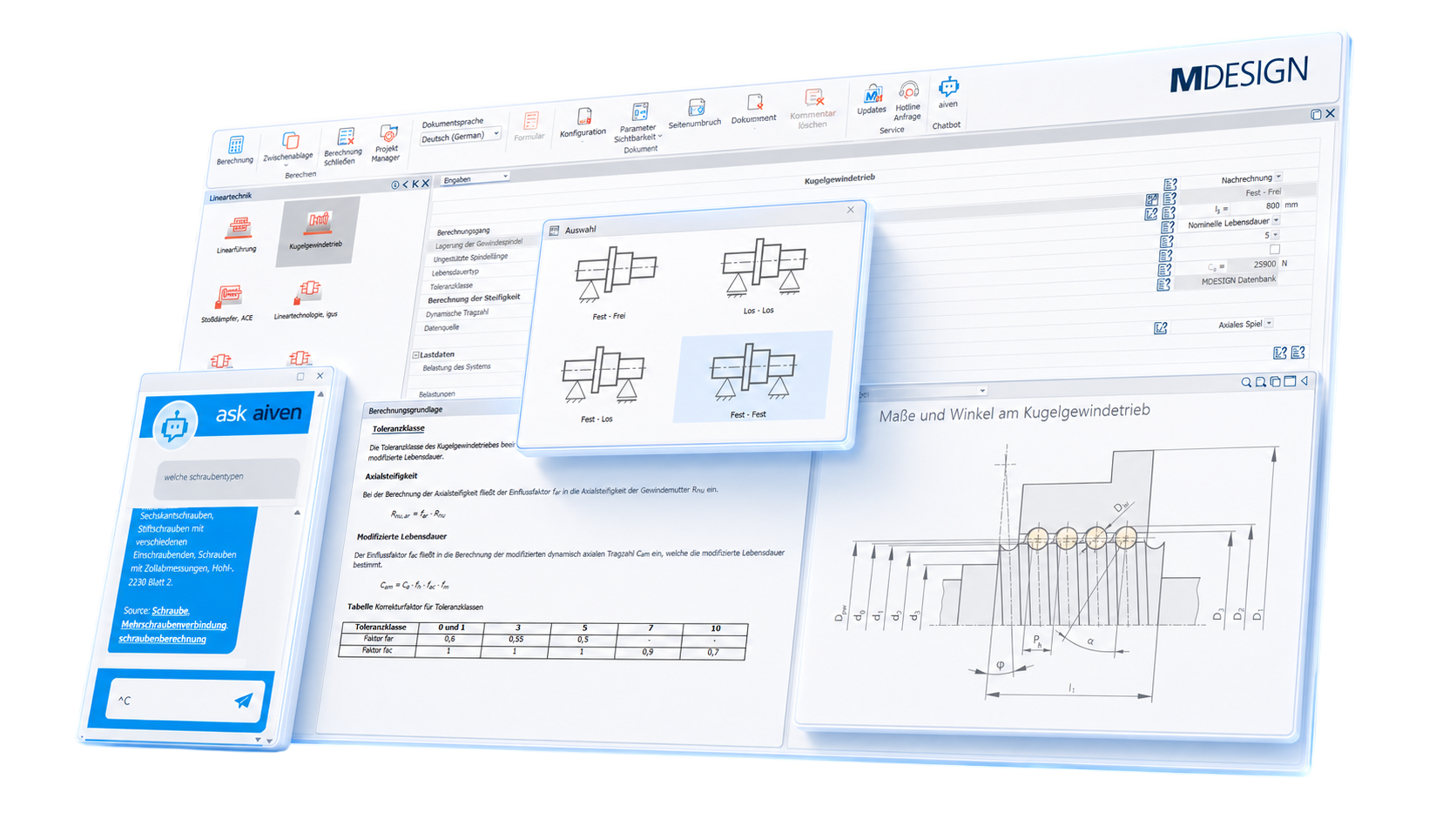
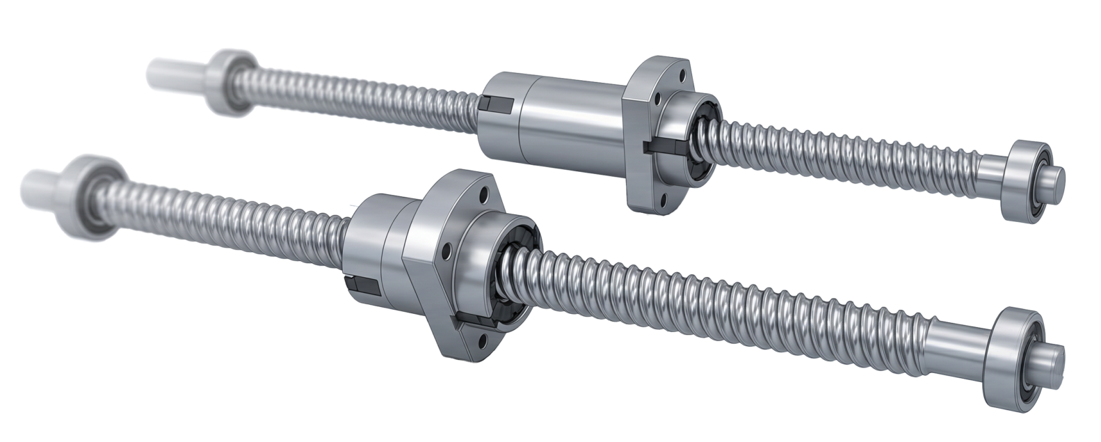
A linear axis must do more than just absorb the forces acting on it. Required service life, accuracy, installation space, and motion dynamics also influence its design. For linear guides, factors such as equivalent loads, static safety, load ratings, and service life are determined. For ball screws, additional factors include axial stiffness, preload, buckling load, and critical and permissible rotational speeds. This makes it clear early on whether a selected size is suitable for the application or whether a different guide, screw geometry, or bearing arrangement is required. This reduces overdimensioning and shortens the process of selecting suitable components.
Select Different Linear Guides Based on Load and Installation Space
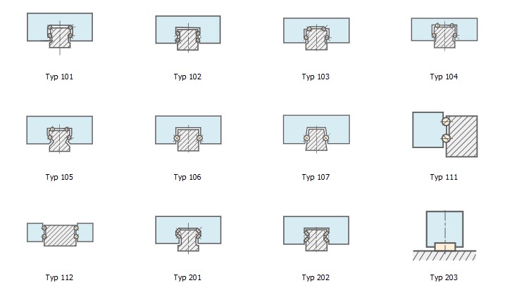
Ball and roller recirculating guides differ in load capacity, design, and load direction. Depending on the machine design, multiple rows of balls or rollers, as well as different guide configurations, may be required.
Various guide types, along with their corresponding load ratings and dimensions, are available for selection and calculation. Both stationary and variable loads can be taken into account, as well as required service life, reliability, and structural safety.
This allows designers to determine early on which guide system meets the required load-bearing capacity within the available installation space.
Linear Guides
Ball Screws
Realistically account for varying loads and speeds
Linear axes rarely operate under a constant load. Different motion phases, forces, rotational speeds, and time intervals determine the actual load throughout the entire work cycle.
Load and speed ranges can therefore be factored into the service life assessment. For ball screws, the bearing type and unsupported spindle length are also taken into account when determining buckling and speed limits.
Thus, the sizing is based not only on a single maximum value, but more closely on the intended motion profile. This provides greater safety for dynamic machine axes and prevents the use of unnecessarily large components.
Understanding Results and Targeted Further Development of Linear Axes
|
01
Guided Input and Results Overview
Structured input fields, help texts, and technical notes provide guidance on loading, geometry, bearings, service life, and stiffness. An AI assistant helps answer questions during the calculation. Results are presented in a clear and organized manner.
|
02
Charts and Technical Graphics
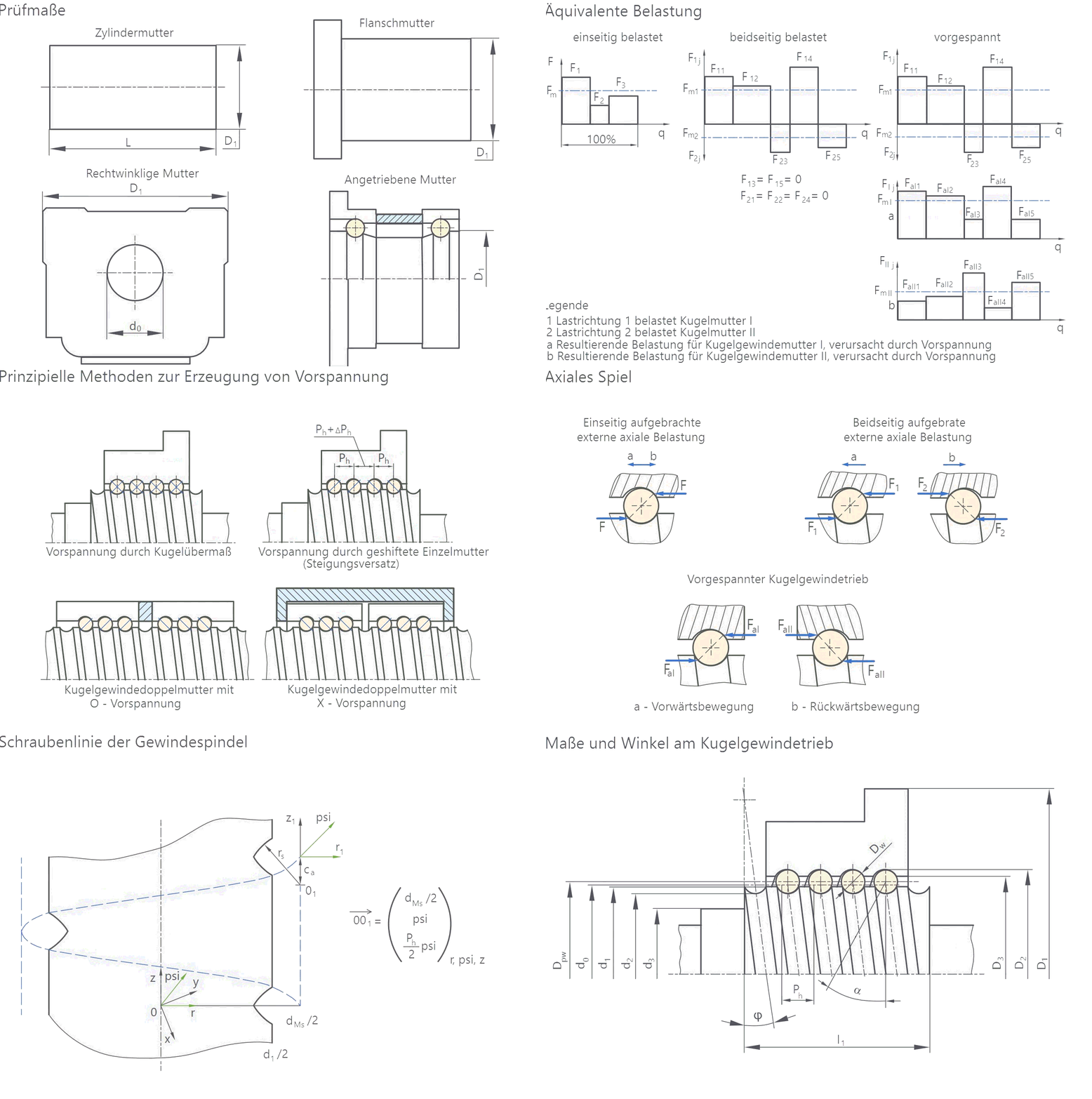
Graphs and diagrams help users understand loads, service life, stiffness, and speed limits. Technical diagrams and illustrative graphics make it easier to understand the calculation parameters and their relationships.
|
Documentation and proof at the touch of a button
Automatically generate technical documentation.
All input data, standards, boundary conditions, results, and graphics are automatically compiled into a complete set of documentation. This results in transparent verification documentation for internal development, customers, testing organizations, or Manufacture.
Features of the MDESIGN Linear Technology
The functions are organized into compact sections covering standards, linear guides, guide types, ball screws, stiffness, and critical speed and buckling load.
-
Standards & Calculation Bases
- DIN 636, Part 2
- ISO 281/A2
- DIN ISO 3408-4
- DIN ISO 3408-5
- Calculation Based on the Literature
-
Linear Guides
Input values
- Type of Load
- Type of guide
- Radial force
- Tangential force
- Percentage of Total Distance Run
- Required Service Life
- Required Reliability
- Required structural safety
- Static load capacity
- Dynamic Load Capacity
- Maximum Permitted Width
- Maximum Permitted Height
- Maximum allowed length
Output values
- Static equivalent load
- Dynamic equivalent load
- Average Equivalent Load
- Structural Safety
- Service life factor
- Service life
- Width of the guide
- Width of the guide rail
- Height of the guide
- Height of the sled
- Height of the guide rail
- Length of the sled
Sample Results Chart
An illustrative graphical analysis of a ball-rail guide. -
Types of Leadership
- Ball screw drives with 4 rows of balls and the same load capacity in all principal directions
- Ball-screw drives with 4 rows of balls and unequal load capacities in the radial, counter-radial, and tangential directions
- Ball-screw drives with 2 rows of balls in a four-point arrangement
- Ball-screw drives with 6 rows of balls
- Ball-circulating roller shoe with two rows of angular contact balls arranged laterally
- Rolling-contact guides with 4 rows of rollers and the same load-carrying capacity in all principal directions
- Circulating roller shoe with a row of rollers
-
Ball screw drive
Input values
- Calculation Run
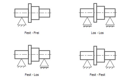
- Mounting the Threaded Spindle
- Unsupported spindle length
- Distance between the bearings
- Lifespan Type
- Tolerance Class
- Calculation of Stiffness
- Outer diameter of the ball screw
- Core diameter of the ball screw
- Bore diameter of the ball screw
- Center Circle Diameter of a Sphere
- Outer diameter of the ball nut body
- Ball diameter
- Slope
- Contact Angle
- Number of load-bearing cycles
- Preload force
- Axial load
- Rotational speed
- Time Share
- Required Service Life
- Reliability
Output values
- Dynamic Load Capacity
- Modified dynamic load rating
- Equivalent Load
- Equivalent rotational speed
- Limit load of a preloaded ball screw
- Critical buckling load
- Permissible axial load
- Critical bending speed
- Permissible speed
- Rated service life
- Service life with reliability correction
- Modified nominal service life
- Modified service life with reliability correction
-
Static axial stiffness
Input values
- System Load
- Preload force
- Mounting the Threaded Spindle
- Unsupported spindle length
- Distance between the bearings
- Tolerance Class
- Center Circle Diameter of a Sphere
- Ball diameter
- Contact Angle
- Number of load-bearing cycles
- Fit between the ball and the nut raceway
- Contact between the ball and the spindle raceway
Output values
- Static axial stiffness of the threaded spindle
- Static axial stiffness of the threaded nut
- Static axial stiffness of the threaded nut, taking the accuracy class into account
- Static Axial Stiffness of the Ball Screw
- Number of load-bearing balls per revolution
- Angle of Inclination
- Cross-sectional area of the ball screw
- Moment of inertia of the ball screw
-
Critical Bending Speed & Buckling Load
Input values
- Storage Method
- Unsupported spindle length
- Core diameter of the ball screw
- Safety factor for the permissible speed
- Safety factor for the allowable axial load
Output values
- Critical bending speed
- Permissible speed
- Critical buckling load
- Permissible axial load
Try it for free – Your access to MDESIGN
Discover for free
Learn about the features
Just get started
No download, no installation
Full Range of services
14 days of access to all sections