Gear calculation for the
decisive edge
in engineering
Gearings Design for performance, service life, and operational safety
Gearings They transmit torque under high contact and alternating loads. Tooth geometry, material, lubrication, speed, and load collectively determine load-carrying capacity, efficiency, wear, and service life.
MDESIGN allows for the standard-compliant design, verification, and documentation of spur gears, bevel gears, worm gears, and other Gearings . From geometry determination and root and flank load-carrying capacity to temperature, wear, and lubricant film analyses, it provides a solid foundation for Design, technical approval, and further development.
Standards and guidelines considered for Gearings and gear design verification
Spur gears
ISO 6336 DIN 3990
Bevel gears
ISO 10300 DIN 3991
Special Tooth Profiles
DIN 3996 VDI 2736/2737
U.S. Standards
AGMA ANSI
Establish Standards, accelerate Engineering
MDESIGN provides a consistent basis for calculations across the entire team. Structured data entry, centrally maintained calculation bases, and consistent documentation ensure that results remain traceable and comparable across projects.
For over 40 years, MDESIGN has been helping companies calculate and design technical components—today with more than 35,000 users worldwide.

Comprehensively evaluate gear geometry and operational behavior
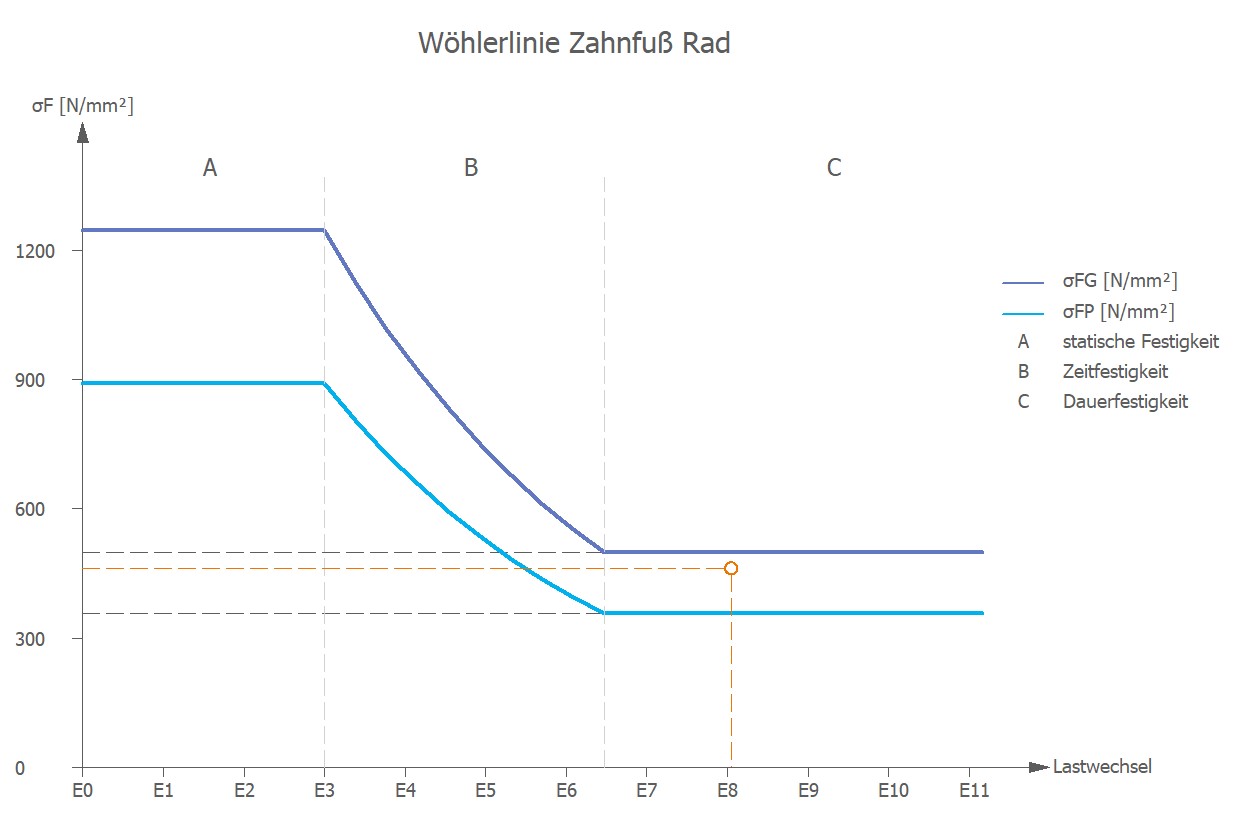
To ensure a robust design, numerous influencing factors must be considered together. These include, among others, module, tooth width, profile offset, and center distance, as well as torque, rotational speed, material, lubrication, and load distribution. Depending on the type of gearing, this data is used to determine geometric parameters, tooth forces, stresses, safety factors, contact parameters, efficiency, power loss, temperature values, tolerances, and lubrication conditions. Advanced analyses also enable evaluations of wear, gray spots, tooth flank fracture, or deformation. This not only allows engineers to verify whether a gear system is fundamentally capable of withstanding the loads but also enables them to see how changes to geometry, material, or operating conditions affect running behavior, safety margins, efficiency, and service life.
Quickly Select Suitable Materials and Lubricants
Standardized materials for pinions and gears are available for selection directly within the calculation. The database includes not only the material designation and material number, but also the parameters relevant to gear tooth calculation—such as strength values, heat treatment condition, modulus of elasticity, density, hardness, and associated standards and sources.
Map material combinations in the calculation scenario
The material selection can be performed separately for the pinion and the gear. Different material combinations and heat treatments can thus be directly modeled in the respective calculation scenario without having to manually transfer the required property values from tables.
In addition to the existing data, users can add their own materials, internal properties, and company-specific material data and reuse them for future projects. This allows standard materials and company-specific specifications to be used within the same database.
Define the pinion and gear separately and model different material combinations.
Use strength, hardness, density, modulus of elasticity, and other values directly.
Take into account viscosity, density, FZG hardness grade, lubrication type, and temperatures.
Lubricant data is also incorporated directly into the calculation, depending on the selected verification method. This includes, among other things, viscosity, density, FZG friction grade, lubrication type, as well as oil and operating temperatures. This allows the material pairing and lubrication conditions to be jointly tailored to the actual application.
Additional reliability for demanding gear applications
In addition to standard load-carrying capacity calculations, MDESIGN also supports special verification procedures when lubrication, material, temperature, or deformation have a significant impact on the application.
Depending on the module, lubricant film thickness, local contact stresses, deformation, or twist-flank clearance can also be taken into account.
Available types of gear teeth in MDESIGN
MDESIGN covers a wide range of gear types and transmission designs. Depending on the application, dedicated calculation modules are available, each with the appropriate geometric, load, and design parameters.
This allows both standard and more specialized Gearings to be edited within the same software environment.
 Spur gears
 Gear racks
 Bevel & Hypoid Gears
 Worm gears
 Crown gears
Plastic gears
Screw gears
Crown gears
Plastic gears
Screw gears Hollow gears
Planetary Gears
Hollow gears
Planetary Gears
Understanding Results and Further Developing " Gearings " in a Targeted Manner
|
01
Guided and Structured Input
Assistance with entering the relevant geometry, material, and operating data. Help texts, technical notes, and an integrated AI assistant make your work easier right within the software.
|
02
3D representation of the gear geometry
The calculated gear meshing is displayed as a 3D model. This allows users to directly visualize the tooth profile, dimensions, and geometric relationships and compare them with the entered parameters.
|
Documentation and proof at the touch of a button
Automatically generate technical documentation.
All input data, standards, boundary conditions, results, and graphics are automatically compiled into a complete set of documentation. This results in transparent verification documentation for internal development, customers, testing organizations, or Manufacture.
STEP Export Directly from the Calculation
Components are modeled, analyzed, and evaluated in MDESIGN . The validated results can then be exported directly as STEP files and transferred to CAD systems. This ensures that the entire development process remains consistent—without any data discontinuities or the need for manual geometry transfer.




Features of the " MDESIGN " Gear Design Calculation
The most important calculation modules are listed individually. For each type of gear, the key input values and the results calculated from them are presented side by side.
01
Calculation Bases & Standards
Geometry and load-bearing capacity calculations based on standards and the literature.
Calculation Bases & Standards
Geometry and load-bearing capacity calculations based on standards and the literature.
Depending on the type of gear teeth and the required verification, the applicable national and international standards are used.
02
Design of Spur Gear Pairs
Preliminary design of a pair of spur gears based on the gear ratio, center distance, load, and material.
Design of Spur Gear Pairs
Preliminary design of a pair of spur gears based on the gear ratio, center distance, load, and material.
The design module determines a suitable basic geometry and indicates which design approach is decisive for module selection.
Input values
Calculated Results
03
Spur Gear Calculation
Comprehensive geometry, tolerance, and load-carrying capacity calculations for external and internal gear teeth.
Spur Gear Calculation
Comprehensive geometry, tolerance, and load-carrying capacity calculations for external and internal gear teeth.
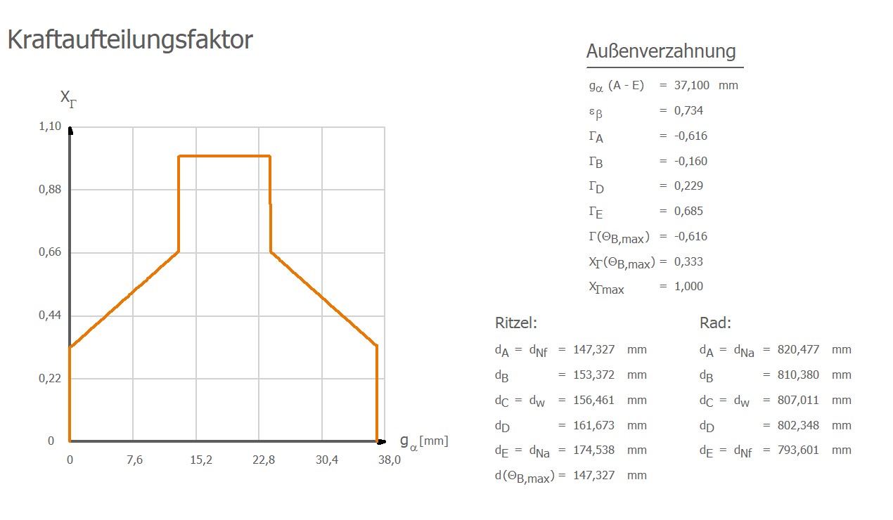
Straight, helical, and double-helical spur gears can be geometrically designed and rated according to various load-carrying capacity standards.
Input values
Calculated Results
04
Spur Gear-Rack Connections
Geometric and Strength Analysis for Pinion-Rack Systems.
Spur Gear-Rack Connections
Geometric and Strength Analysis for Pinion-Rack Systems.
The calculation takes into account the specific geometry and load transfer between a spur gear and a linear rack.
Input values
Calculated Results

05
Bevel & Hypoid Gears
Geometry and load-carrying capacity calculations for bevel and hypoid gears.
Bevel & Hypoid Gears
Geometry and load-carrying capacity calculations for bevel and hypoid gears.
Bevel and hypoid gears are calculated taking into account the axis angle, axis offset, manufacturing process, and spatial gear tooth geometry.
Input values
Calculated Results
06
Worm gear
Calculation of load capacity, efficiency, temperature, and wear in accordance with DIN 3996.
Worm gear
Calculation of load capacity, efficiency, temperature, and wear in accordance with DIN 3996.
The worm gear and worm wheel are evaluated as an integrated system comprising geometry, bearings, lubrication, power loss, and thermal load.
Input values
Calculated Results
07
Helical Gear Drive
Geometric and load-carrying capacity calculations for crossed helical gears.
Helical Gear Drive
Geometric and load-carrying capacity calculations for crossed helical gears.
Helical gears are calculated based on the axis angle, different helix angles, profile offsets, and the specific sliding conditions.
Input values
Calculated Results

08
Bevel Gear Drive
Design and Strength Analysis for Pinion-Crown Wheel Pairs.
Bevel Gear Drive
Design and Strength Analysis for Pinion-Crown Wheel Pairs.
The crown gear module takes into account the radially variable tooth geometry, usable diameter ranges, and the load-carrying capacity of the gear pair.
Input values
Calculated Results

09
Plastic gears
Geometric, temperature, wear, and load-carrying capacity calculations in accordance with VDI 2736.
Plastic gears
Geometric, temperature, wear, and load-carrying capacity calculations in accordance with VDI 2736.
Plastic gears are evaluated taking into account temperature-dependent material properties, the type of lubrication, deformation, and wear.
Input values
Calculated Results
10
Bevel gear with ring gear influence
Tooth root load-carrying capacity of elastic internal gear teeth according to VDI 2737.
Bevel gear with ring gear influence
Tooth root load-carrying capacity of elastic internal gear teeth according to VDI 2737.
This module evaluates how an elastic gear ring and stiffening connecting components affect the stress at the tooth root of a hollow gear.
Input values
Calculated Results
11
Gray-spotted carrying capacity
Assessment of the risk of gray spots along the tooth-to-tooth contact area in accordance with ISO/TS 6336-22.
Gray-spotted carrying capacity
Assessment of the risk of gray spots along the tooth-to-tooth contact area in accordance with ISO/TS 6336-22.
The calculation examines local lubrication and contact conditions at several points along the contact path.
Input values
Calculated Results

12
Tooth flank fracture
Local material verification against tooth flank fracture in accordance with ISO/TS 6336-4.
Tooth flank fracture
Local material verification against tooth flank fracture in accordance with ISO/TS 6336-4.
The analysis evaluates the local stress in the material beneath the tooth flank, taking into account the depth of hardening, the hardness profile, and residual stresses.
Input values
Calculated Results

13
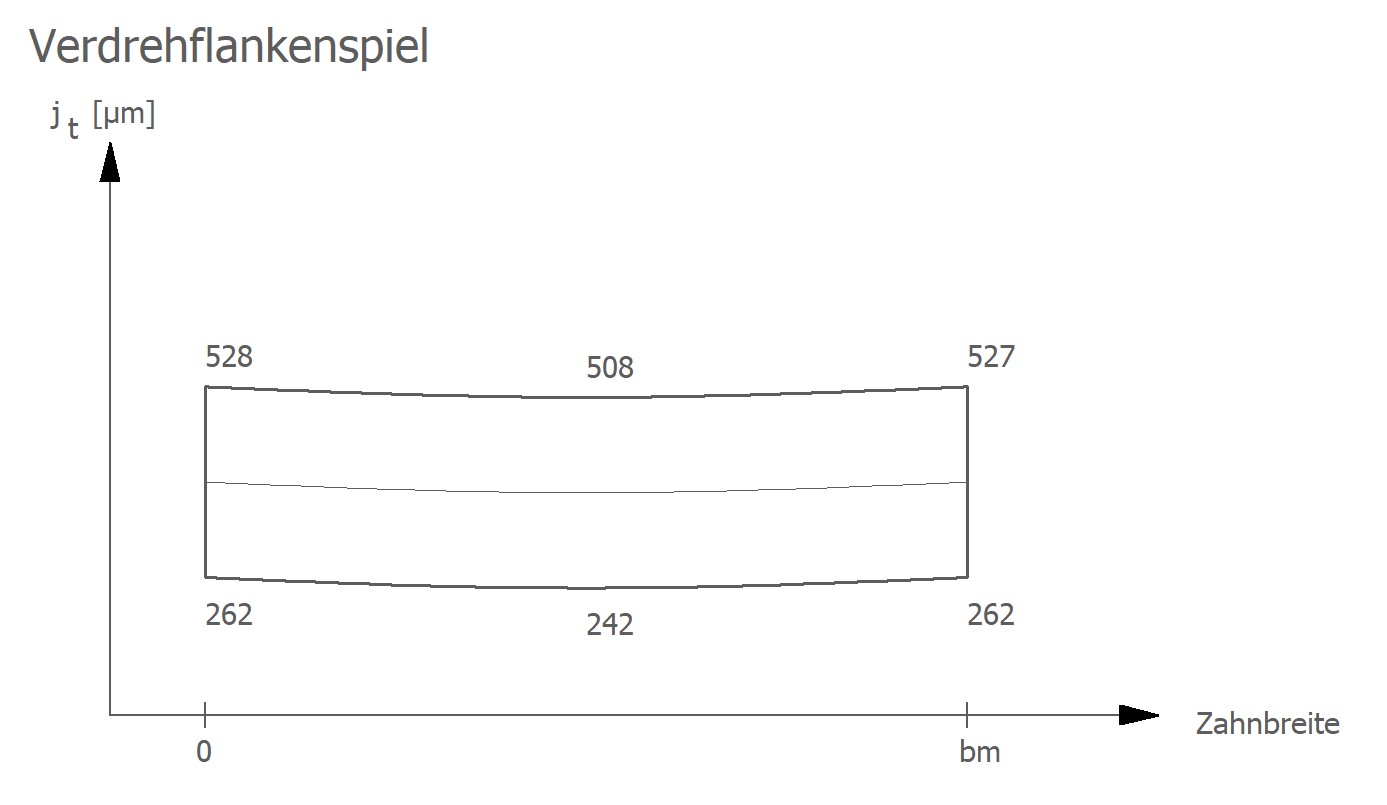
Torsional backlash
Calculation of tolerance and deformation of the flank clearance across the tooth width.
Torsional backlash
Calculation of tolerance and deformation of the flank clearance across the tooth width.
The theoretical and operational helical flank clearance is determined by tooth thickness deviations, center distance tolerances, flank modifications, and shaft deformations.
Input values
Calculated Results
14
Materials & Lubricants
Material, hardness, temperature, and lubricant properties for gear design verification.
Materials & Lubricants
Material, hardness, temperature, and lubricant properties for gear design verification.
The required strength, elasticity, hardness, and lubricant data are taken into account depending on the specific calculation module. In addition, internal materials can be stored in a company database
15
Results & Analyses
Module-specific output of geometry, loading, load-bearing capacity, and operational safety.
Results & Analyses
Module-specific output of geometry, loading, load-bearing capacity, and operational safety.
The output results depend on the type of gearing and the selected verification method.
Try it for free – Your access to MDESIGN
Discover for free
Learn About the Features
Just Get Started
No download, no installation
Full Range of Services
14 days of access to all sections