Piping Design for
Efficient and Reliable Systems
Identify critical pressure drops and stresses early on and provide targeted protection for piping systems.
Consider flow and strength together from the very beginning
Piping systems must reliably transport fluids while withstanding the pressures, temperatures, and operating conditions they encounter. Therefore, it is crucial not only to minimize pressure loss but also to provide robust evidence that the pipes and components are suitable for the intended operating conditions.
MDESIGN allows you to calculate, analyze, and document Pipelines in accordance with standards—from hydraulic design to strength verification in accordance with DIN EN 13480-3. This provides a transparent basis for calculations design, technical inspection, and acceptance, thereby ensuring greater reliability throughout the entire design process.
Establish standards, accelerate engineering
MDESIGN provides a consistent basis for calculations across the entire team. Structured data entry, centrally maintained calculation bases, and consistent documentation ensure that results remain traceable and comparable across projects.
For over 40 years, MDESIGN has been helping companies calculate and design technical components—today with more than 35,000 users worldwide.

Determine pressure losses and required pump capacity
Every bend, valve, and change in cross-section affects flow resistance. Across the entire piping network, these losses add up and determine the actual delivery capacity required. MDESIGN process calculates total pressure loss, flow velocity, Reynolds numbers, and pipe friction losses, among other parameters. The required pump performance can be derived directly from this data. This allows pipe diameters and conveyance systems to be optimally matched to one another. Unnecessary performance margins can be avoided, while simultaneously revealing early on where particularly high losses occur in the system.
Mapping the pipeline network using real components
Straight pipe sections are only one part of the overall system. Elbows, reducers, branches, valves, and other fittings can alter the flow pattern and resistance, in some cases significantly.
In MDESIGN, these elements can be combined within a coherent model. geometries, connection types, and directional changes can be set up to match the actual design.
This makes it possible to understand the impact that individual components have on the overall system. Variations in the pipeline layout can be compared at an earlier stage, and unfavorable flow paths can be identified as early as the planning phase.
Compare operating, test, and temperature conditions
Normal operation, pressure testing, or temperature fluctuations place varying stresses on a piping system. Depending on the situation, a different parameter may therefore be decisive for sizing.
A direct comparison of these conditions shows whether the selected design functions only under normal operating conditions or whether it also adequately covers test and special conditions.
This allows critical load cases to be identified early on and taken into account in the Design even before approval or acceptance.
Water & brine
Water,MgCl₂ brine
Fuels & combustibles
Gasoline, diesel fuel, heating oil, methylated spirits
Oils
Petroleum, spindle oil
Food & beverage
Beer, wine, milk
Industrial fluids
Glycerin, Frigen
In addition, users can create their own media, material properties such as density or viscosity, and company-specific data sets, which can then be used for recurring pipeline calculations.
Use material properties appropriate for the temperature
The permissible stress on a material does not remain constant across the entire temperature range. Particularly in the case of thermally stressed lines, the same material can have significantly different safety margins depending on operating conditions.
Temperature-dependent stress values, moduli of elasticity, and other relevant properties are stored for numerous pipe materials and can be used directly for the respective load case.
Company-specific materials and internal parameters can also be added. This ensures that recurring calculations draw on the same database without having to repeatedly search for or transfer values.
Translate results into concrete system decisions
Once the calculation is complete, all relevant results are presented in a structured and transparent manner. These include, among other things, pressure losses, pump capacities, Reynolds numbers, flow velocities, wall thicknesses, stresses, and maximum allowable pressures.
Graphical representations make it easier to quickly assess the piping system and support targeted optimization even during the design phase.

01
Guided data entry and structured analysis
The interface assists with calculations and clearly summarizes hydraulic and mechanical parameters. This makes it easy to quickly record, compare, and verify pressure losses, flow velocities, Reynolds numbers, and pump performance.
|
02
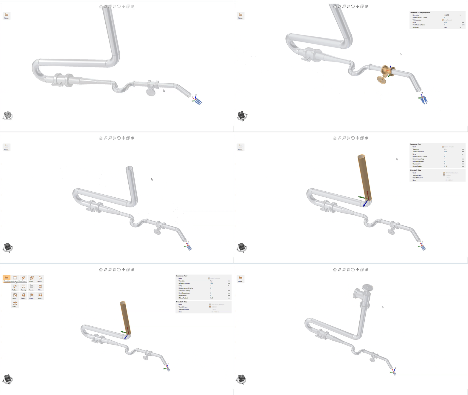
Building piping systems in a 3D model
The built-in 3D wizard makes pipe routes, components, and changes in direction immediately visible. This allows even complex networks to be set up clearly and geometric adjustments to be understood at a glance.
|
Documentation and proof at the touch of a button
Automatically generate technical documentation.
All input data, standards, boundary conditions, results, and graphics are automatically compiled into a complete set of documentation. This results in transparent verification documentation for internal development, customers, testing organizations, or manufacture.
STEP export directly from the calculation
Components are modeled, analyzed, and evaluated in MDESIGN. The validated results can then be exported directly as STEP files and transferred to CAD systems. This ensures that the entire development process remains consistent—without any data discontinuities or the need for manual geometry transfer.




Features of MDESIGN piping calculation
The functions are organized into concise categories based on standards, piping systems, pressure loss, strength analysis, media, materials, and results.
-
Standards & calculation bases
- DIN EN 13480-3
- Calculation based on the literature
-
Piping systems & elements
- Pipe
- Pipe elbow
- Cast iron 90° elbow
- Reducer, continuous
- Reducer, sudden
- Branch
- Pipe inlet
- Pipe outlet
- Straight-through valve
- Angle valve
- Gate valve without a guide tube
- Check valve
- Full-bore faucet
-
Pressure drop calculation
Input values
- Pipeline elements
- Outer and inner diameter
- Wall thickness and length
- Average roughness
- Density of the medium
- Kinematic viscosity
- Volume flow or mass flow
- Pump efficiency
- Geodetic elevation difference
Output values
- Flow velocity
- Reynolds number
- Pipe friction coefficient
- Resistance coefficient
- Sum of the resistance values
- Length of the pipeline
- Total pressure loss
- Required pump capacity
- End position of the pipe
-
Strength verification according to EN 13480-3
Input values
- Outer and inner diameter
- Specified wall thickness
- Nominal wall thickness
- Corrosion surcharge
- Manufacturing tolerance
- Bending tolerance
- Calculation pressure
- Temperature
- Weld seam factor
- Radius of curvature and angle of curvature
- Opening angle
Output values
- Calculated wall thickness
- Required minimum wall thickness
- Required minimum wall thickness on the inner and outer surfaces of the bend
- Required minimum wall thickness, including allowances and tolerances
- Permissible voltage
- Average tension on the inner and outer sides of the bow
- Safety factor
- Maximum allowable pressure
- Condition met
Pipeline Components in Strength Analysis
- Straight pipes
- Pipe elbows
- Reducers
- Branches
-
Medium & load data
- Medium
- Density
- Kinematic viscosity
- Internal pressure during operation
- Internal pressure during testing
- External pressure during operation
- External pressure during testing
- Operating temperature
- Temperature during testing
- Volume flow
- Mass flow
- Pump efficiency
- Weld seam factor
-
Materials & properties
- Tensile strength
- 0.2 % yield point
- 1.0 % yield point
- Minimum elongation at break
- Modulus of elasticity
- Density
- Temperature-dependent material properties
- Permissible voltage
-
Results & analyses
- Flow velocity
- Reynolds number
- Pipe friction coefficient
- Resistance values
- Total pressure loss
- Required pump capacity
- Calculated wall thickness
- Required minimum wall thickness
- Maximum allowable pressure
- Permissible voltage
- Safety factor
- Condition met
Try it for free – Your access to MDESIGN
Discover for free
Learn about the features
Just get started
No download, no installation
Full range of services
14 days of access to all sections