
Hydraulics Calculate for
High-Performance Structures
Coordinate forces, pressure levels, and flow rates so that hydraulic systems operate reliably under actual operating conditions.
Balance forces, pressures, and throughput correctly from the very beginning
Hydraulic systems transmit high forces within a relatively small installation space. To ensure that presses, lifting devices, pipelines, or pumps operate as intended, the pressure level, geometry, flow rate, and load must be properly matched.
MDESIGN allows you to perform structured calculations and documentation for typical tasks in the field of hydraulics —from hydraulic presses and lifting jacks to pipe wall thicknesses and the required pump capacity. This provides a reliable basis for design, technical evaluation, and subsequent operation.
Standards Used for Sealing Surfaces and Pipe Wall Calculations
Sealing surface compression
DIN EN 1514
Pipe wall thickness calculation
DIN 2413
Establish standards, accelerate engineering
MDESIGN provides a consistent basis for calculations across the entire team. Structured data entry, centrally maintained calculation bases, and consistent documentation ensure that results remain traceable and comparable across projects.
For over 40 years, MDESIGN has been helping companies calculate and design technical components—today with more than 35,000 users worldwide.
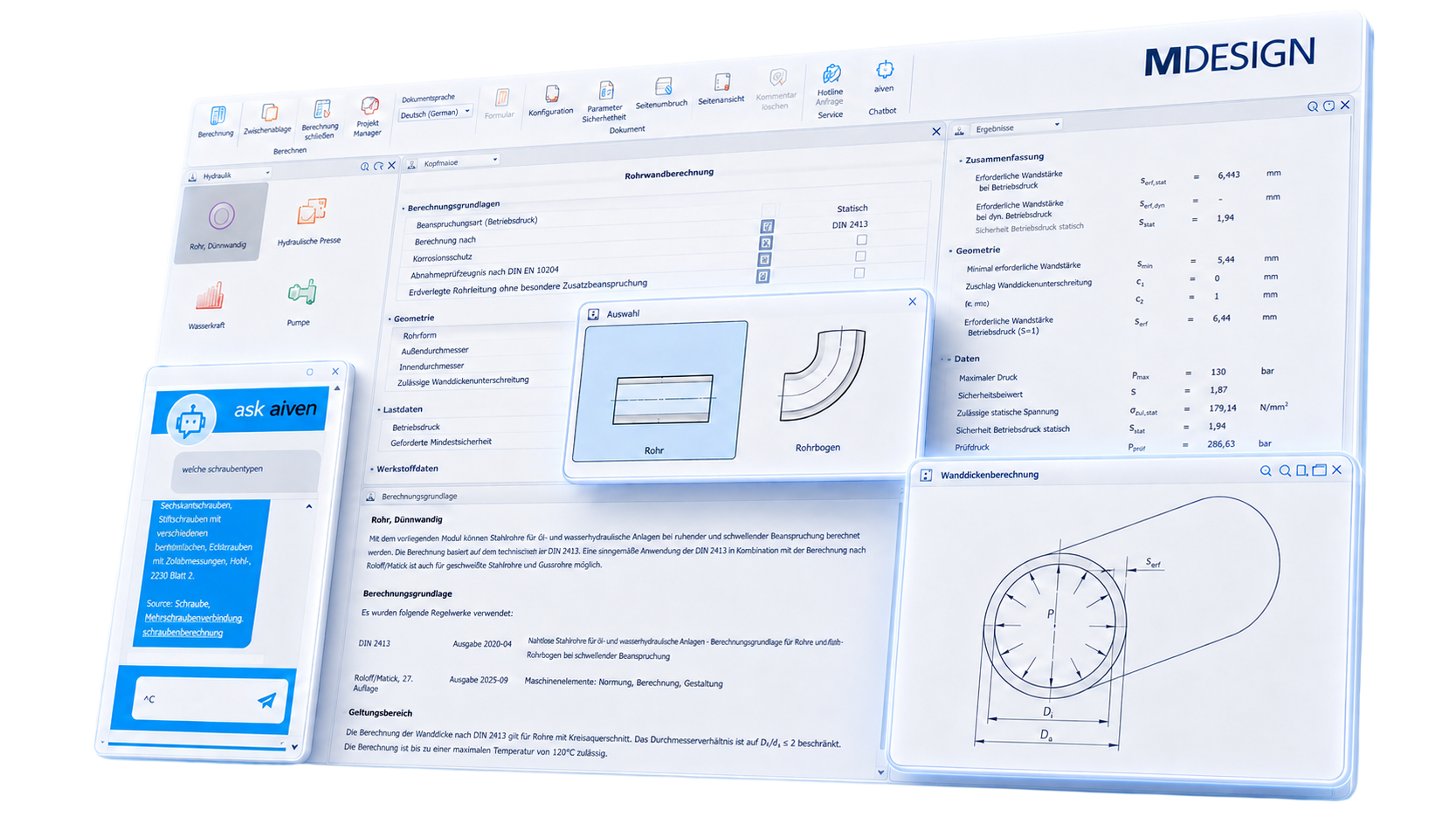
From the required force to the necessary system pressure
In hydraulic presses and lifting devices, the usable force results from the interaction of pressure and effective piston area. Even small changes in these parameters can significantly affect the required design specifications. The required system parameters can be derived from specified forces, areas, or pressure values. This makes it clear early on what pressure level is needed and how large the pistons or cylinders must be designed. Instead of estimating individual parameters independently of one another, the system can be specifically sized for the actual application.
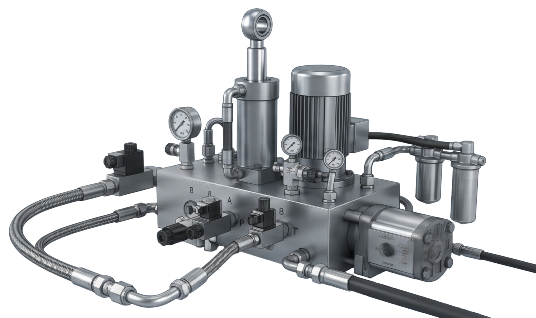
Determine the pump capacity appropriate for the pumping application
The amount of power a pump requires does not depend on a single factor. Flow rate, pressure differential, head, time, and the properties of the fluid are all directly interrelated.
Depending on the application, different input parameters can be used to determine the required capacity for a specific pumping scenario. This makes it easier to assess whether an existing pump is sufficient or what capacity is needed for a new design.
This helps in selecting pumps more precisely, avoiding unnecessary oversizing, and assessing the system’s energy requirements more realistically during the design.
Incorporate operating conditions directly into the design
Pressure fluctuations, varying flow rates, and temperature changes affect the behavior of hydraulic components during operation. In particular, the viscosity of the oil can change significantly with temperature, thereby influencing flow velocity, losses, and power requirements.
These boundary conditions can be defined to suit the specific application and their effects on Pipelines, pump systems, and hydraulic power transmissions can be analyzed.
This provides a more realistic picture of the application. Critical operating conditions become apparent earlier, and components can be sized not only for an idealized rated condition, but for their actual intended use.
Use the results to adjust the flow rate as needed
Once the calculation is complete, the relevant input and output values are displayed in a structured format. Depending on the specific calculation, these include, among other things, pressure, force, volumetric flow rate, pump capacity, flow characteristics, and safety factors.
The clear presentation makes it easy to directly compare the calculated values and ensures that the results can be used immediately for further design steps and technical documentation.
|
01
Structured input and results overview
Help texts, technical notes, and a built-in AI assistant guide users through the workflow directly within the software, making it easier to perform even less common hydraulic calculations.
|
02
Understanding hydraulic systems
Diagrams and technical illustrations help visualize hydraulic relationships and assist in interpreting input data and results.
|
Documentation and proof at the touch of a button
Automatically generate technical documentation.
All input data, standards, boundary conditions, results, and graphics are automatically compiled into a complete set of documentation. This results in transparent verification documentation for internal development, customers, testing organizations, or manufacture.
Features of the MDESIGN hydraulic calculation tool
The functions are organized into the following categories: standards, hydraulic presses, pump capacity, pipe flow, oil viscosity, pipe wall calculations, sealing surface pressure, and hydropower.
-
Standards & calculation bases
- DIN EN 1514
- DIN ISO 3448
- DIN 2413
- Calculation based on the literature
-
Hydraulic press
Input values
- Force on the piston
- Force on the working piston
- Diameter of the piston
- Diameter of the working piston
- Stroke of the pressure piston
- Stroke of the working piston
Output values
- Required diameter of the piston
- Required diameter of the working piston
- Piston area of the pressure piston
- Piston area of the working piston
- Stroke of the pressure piston
- Stroke of the working piston
- Force on the piston
- Force on the working piston
- Fluid overpressure
-
Pump Capacity
Input values
- Calculation procedure
- Pump capacity
- Pressure difference
- Funding period
- Volume flow
- Delivery head
- Density
- Efficiency
Output values
- Pump Capacity
-
Flow velocity & inner pipe diameter
Input values
- Calculation procedure
- Volume flow
- Mass flow
- Density
- Inner diameter of the pipe
- Flow velocity
Output values
- Flow velocity
- Required inner pipe diameter
-
Reynolds number & flow regime
Input values
- Flow velocity
- Inner diameter of the pipe
- Kinematic viscosity
Output values
- Reynolds number
- Critical flow velocity
- Laminar Flow
- Turbulent Flow
-
Oil viscosity
Input values
- ISO VG Viscosity Class
- Bulk density at 15 °C
- Operating temperature of the lubricant
Output values
- Density of the lubricant at operating temperature
- Dynamic viscosity at operating temperature
- Kinematic viscosity at operating temperature
-
Pipe wall thickness calculation
Input values
- Type of load
- Outer diameter
- Inner diameter
- Permissible deviation from minimum wall thickness
- Operating pressure
- Required minimum security
- Yield strength
- Tensile strength
- Elongation at break
- Corrosion protection
- Acceptance test certificate in accordance with DIN EN 10204
- Underground piping without any special additional stress
Output values
- Minimum required wall thickness
- Surcharge for wall thickness deficiency
- Corrosion allowance
- Required wall thickness at operating pressure
- Required wall thickness at dynamic operating pressure
- Maximum pressure
- Safety factor
- Permissible static stress
- Static operating pressure safety factor
- Test print
-
Sealing surface compression
Input values
- Seal type
- Nominal diameter
- Rated pressure
- Screw material
- Temperature
- Screw type
Output values
- Inner seal diameter
- Outer seal diameter
- Number and size of screws
- Total bolt force
- Average sealing surface pressure
- Tensile strength
- Yield strength
- Thread pitch
- Screw hole diameter
- Wrench size
- Thread flank diameter
- Thread core diameter
- Stress cross-section
- Mother's Rest
- Shaft diameter
- Cross-section of the shaft
- Permissible screw force
- Permissible tightening torque
-
Hydropower
Input values
- Calculation procedure
- Water depth
- Angle
- Width of the flap
Output values
- Compressive force per meter of width
- Total force applied to the flap
- Lever arm
Try it for free – Your access to MDESIGN
Discover for free
Learn about the features
Just get started
No download, no installation
Full range of services
14 days of access to all sections