Shaft-hub connections
Calculate before it gets critical
Finding the Right Connection for High Torques
Shaft-Hub- Shaft s must reliably transmit high torques and forces between the and the hub. Key factors here include not only the geometry and type of connection, but also press fits, material pairings, oversize, and actual operating conditions.
MDESIGN combines these influencing factors in a comprehensive calculation. This reveals which connection transmits the required power, where critical stresses occur, and which geometry is appropriate for the application.
Establish Standards, accelerate Engineering
MDESIGN provides a consistent basis for calculations across the entire team. Structured data entry, centrally maintained calculation bases, and consistent documentation ensure that results remain traceable and comparable across projects.
For over 40 years, MDESIGN has been helping companies calculate and design technical components—today with more than 35,000 users worldwide.
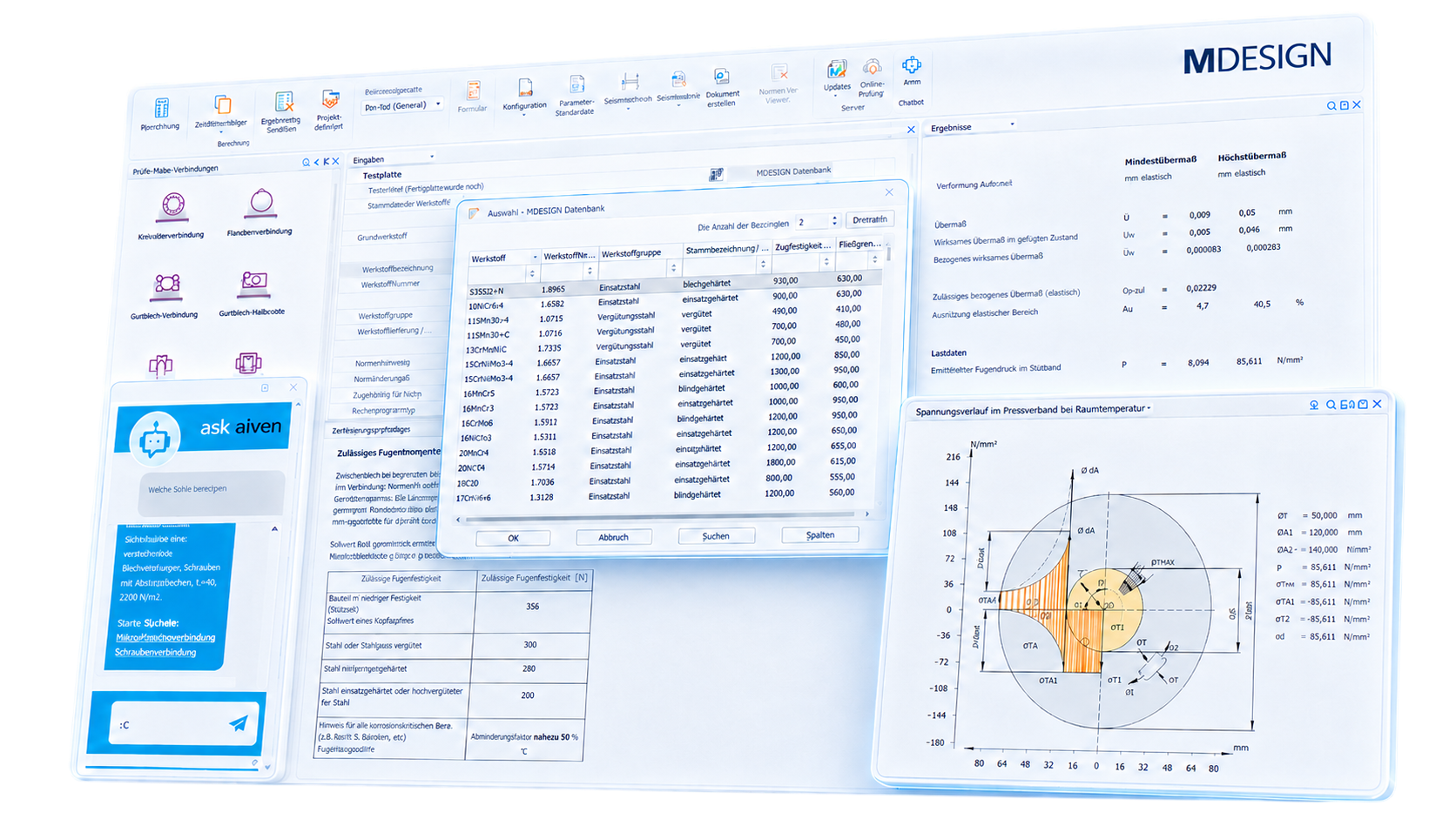
Determine the connection's performance limits
For Shaft hub-to-hub connections, the interplay of torque, geometry, contact pressure, and material determines how strong the connection actually is. MDESIGN calculates, among other things, transmissible torques, surface and flank pressures, joint pressure, required allowances, and safety factors. In addition, geometric parameters and transmissible axial forces can be determined. This allows more than just the verification of an existing connection. Designers can already make targeted assessments during the design phase to determine which geometry is required, where there is margin for improvement, and which variant makes more technical sense. This shortens the number of iterations, reduces unnecessary oversizing, and provides clarity more quickly for further Design.

Select a connection type that is appropriate for the power rating and installation space
Depending on the application, different Shaft hub connections are used. Torque, installation space, mounting conditions, and the type of load significantly influence the selection of the appropriate connection.
It supports a wide range of form-fitting and force-fit connections, making it possible to compare different variants using a uniform calculation basis.
This makes it possible to compare alternatives earlier, identify technical limitations more quickly, and tailor connections more precisely to the specific application.
 V-belt drive
 Keyway connection
 Split disc hub
 Slotted lever hub
 Tapered joint
 Clamping Element Connection
 Cylindrical Compression Bandage
 Conical Compression Bandage
 Gear shaft
 Polygon Profile, P3G
 Polygon Profile, P4C
 Axial stress
 Planker gear teeth
Realistically Simulating Material Combinations and Contact Pressures
Shaft s and hubs often involve a combination of different materials, stiffness levels, and permissible compressive forces. Especially in press-fit assemblies, this combination directly influences the joint pressure that develops and the forces that can be transmitted.
MDESIGN provides comprehensive material data with the relevant properties needed for calculations. In addition, users can add and reuse their own materials, internal properties, and company-specific material data.
This allows real-world material combinations to be directly modeled and ensures that company-specific specifications are consistently incorporated into the design. This improves the comparability of calculations and reduces the effort required to repeatedly compile characteristic values.
Derive better connection designs from calculation results
MDESIGN compares torques, compressive forces, stresses, geometric values, and loads in such a way that the technical relationships become quickly apparent.
This not only makes it possible to determine whether a connection works. Design engineers can also see why a particular variant is reaching its limits and where a change would have the greatest effect—for example, in terms of diameter, oversize, material, or connection type.
This allows for more targeted development of variants, better utilization of installation space, and faster decision-making between different Shaft hub concepts.
01
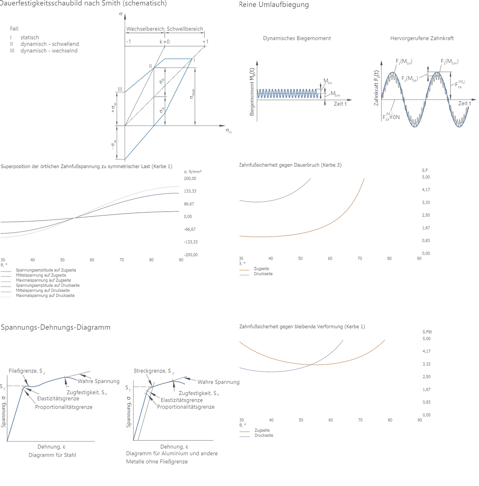
Automatically Generated Charts
Analyses show whether flange compression, joint compression, tension, or load-bearing capacity is the determining factor for the joint. This makes it clear where design efforts should be focused and which modifications actually affect the joint’s performance.
|
02
Intuitive User Interface
A structured interface, guided input, help texts, calculation principles, and AI assistance also make it easier to work with less common connection types. This allows designers to handle even complex Shaft hub connections more independently.
|
Documentation and proof at the touch of a button
Automatically generate technical documentation.
All input data, standards, boundary conditions, results, and graphics are automatically compiled into a complete set of documentation. This results in transparent verification documentation for internal development, customers, testing organizations, or Manufacture.
Features of the MDESIGN Shaft Hub Connections
The most important calculation modules are listed individually. Only technically closely related connections with comparable input values and results are presented together.
01
Calculation Bases & Standards
Calculation of various Shaft hub connections based on standards and the literature.
Calculation Bases & Standards
Calculation of various Shaft hub connections based on standards and the literature.
Depending on the type of connection, the appropriate standards, guidelines, and technical literature are used as the basis for calculations.
02
Toothed and Splined Shaft Connections
Geometric and load-bearing capacity analysis of profiled Shaft hub connections.
Toothed and Splined Shaft Connections
Geometric and load-bearing capacity analysis of profiled Shaft hub connections.
Splined and keyed shafts are calculated in terms of profile geometry, flank pressure, load distribution, and flank safety.
Input values
Calculated Results
03
Planker gearing
Detailed load-bearing capacity calculation for Hirth-Gearings s with screw connections.
Planker gearing
Detailed load-bearing capacity calculation for Hirth-Gearings s with screw connections.
The Planker gearing is evaluated for central or decentralized bolting under combined axial, radial, torsional, and bending loads.
Input values
Calculated Results

04
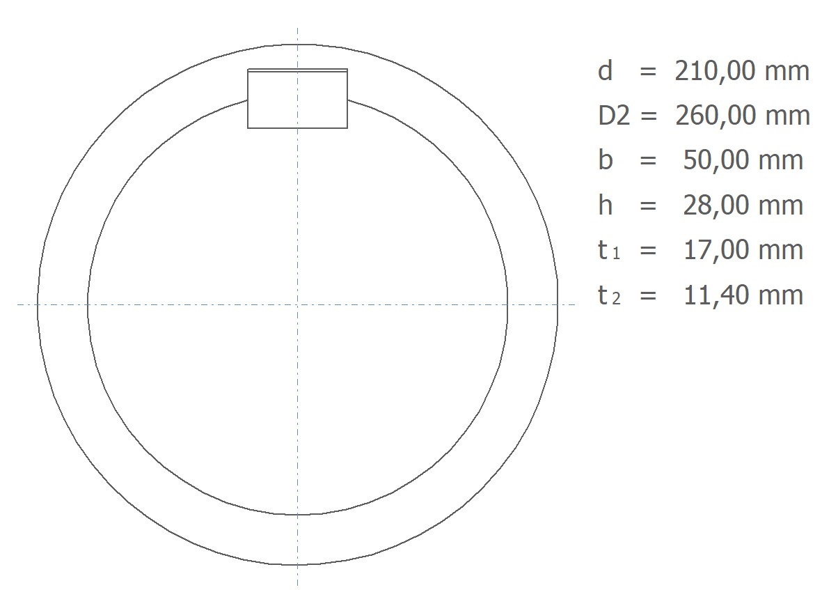
Keyway connections
Calculation in accordance with DIN 6885 and DIN 6892 using Method B or C.
Keyway connections
Calculation in accordance with DIN 6885 and DIN 6892 using Method B or C.
Keyway connections are evaluated in terms of effective geometry, surface pressure, and transmissible torques.
Input values
Calculated Results
05
P3G & P4C Polygon Profiles
Geometric and strength calculations in accordance with DIN 32711 and DIN 32712.
P3G & P4C Polygon Profiles
Geometric and strength calculations in accordance with DIN 32711 and DIN 32712.
P3G and P4C profiles have a similar calculation structure and are therefore presented together.
Input values
Calculated Results
06
Cylindrical Compression Bandages
Calculation of longitudinal and transverse compression bracing systems in accordance with DIN 7190-1.
Cylindrical Compression Bandages
Calculation of longitudinal and transverse compression bracing systems in accordance with DIN 7190-1.
Cylindrical press fits are designed or verified based on interference fit, oversize, joint pressure, friction, and component stresses.
Input values
Calculated Results

07
Conical Compression Bandages
Calculation of self-locking tapered press fits according to DIN 7190-2.
Conical Compression Bandages
Calculation of self-locking tapered press fits according to DIN 7190-2.
Conical compression joints are evaluated for resistance to slippage, loosening, and plasticization based on the slip distance, oversize, joint pressure, and the Safeties .
Input values
Calculated Results

08
Tapered Joints
Calculation based on published literature in accordance with * Roloff/Matek * and DIN 254.
Tapered Joints
Calculation based on published literature in accordance with * Roloff/Matek * and DIN 254.
Conventional tapered joints are calculated in terms of press-fit force, joint compression, interference fit, slide-on travel, and self-locking.
Input values
Calculated Results
09
Clamping Element Connections
Selection and sizing of clamping elements based on torque or axial force.
Clamping Element Connections
Selection and sizing of clamping elements based on torque or axial force.
Clamping elements are selected and evaluated based on the load, the available Shafts, and the hub geometry.
Input values
Calculated Results
10
Slotted lever hub & split disc hub
Screw-clamped hubs with comparable input and output values.
Slotted lever hub & split disc hub
Screw-clamped hubs with comparable input and output values.
Both types of hubs are calculated according to Roloff/Matek based on joint compression, frictional engagement, and required clamping forces.
Input values
Calculated Results
11
Axial stress
Calculation of axially prestressed clamped joints according to Schlottmann.
Axial stress
Calculation of axially prestressed clamped joints according to Schlottmann.
The joint is sized based on the friction surface, rated torque, and required clamping force.
Input values
Calculated Results
12
Materials & Properties
Material data for Shaft, hub, key, screws, and fasteners.
Materials & Properties
Material data for Shaft, hub, key, screws, and fasteners.
The material selection is performed separately for each component involved, depending on the calculation module.
Try it for free – Your access to MDESIGN
Discover for free
Learn About the Features
Just Get Started
No download, no installation
Full Range of Services
14 days of access to all sections