From the load directly
to the right shock absorber
Select suitable industrial shock absorbers based on original ACE product data and specifically evaluate different application scenarios and load conditions.
Shock absorber selection using original ACE product data
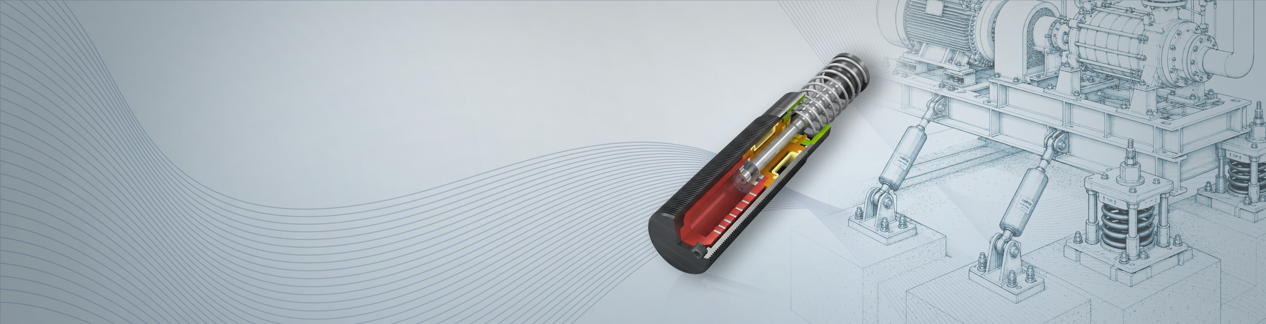
Shock absorbers protect machinery and equipment from impact loads, reduce peak loads, and extend the service life of components. To help select suitable industrial shock absorbers, MDESIGN offers an integrated calculation and selection system based on the ACE product databases.
Unlike traditional calculation modules, the design process does not rely on general calculation methods, but rather on the original ACE selection and calculation algorithms. Based on just a few inputs, suitable shock absorbers are suggested immediately, including part numbers, technical data, and contact information.
Establish standards, accelerate engineering
MDESIGN provides a consistent basis for calculations across the entire team. Structured data entry, centrally maintained calculation bases, and consistent documentation ensure that results remain traceable and comparable across projects.
For over 40 years, MDESIGN has been helping companies calculate and design technical components—today with more than 35,000 users worldwide.


Select a shock absorber directly from the calculation
MDESIGN and ACE have a long-standing partnership. The selection of suitable shock absorbers takes place directly within the familiar MDESIGN environment, based on the original ACE product databases and selection algorithms.
Find the right shock absorbers in just a few steps
After just a few entries, MDESIGN suggests suitable shock absorbers from the ACE product portfolio.
Conditions at the installation site can also be taken into account. These include ambient temperature, dirt and dust, cooling lubricants, installation in pressurized spaces, emergency stop applications, or requirements for stainless steel versions.
Find the right shock absorber quickly
|
01
Intuitive interface, guided input
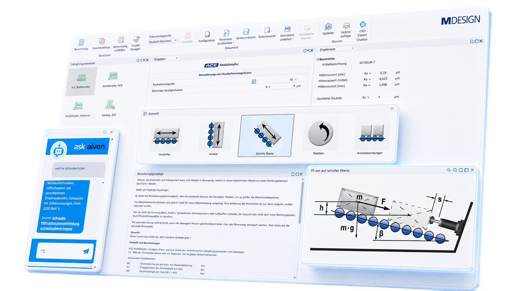
A structured input process guides users through the direction of motion, application, mass, velocity, driving force, and cycle rate. The system then suggests suitable ACE shock absorbers, including part numbers and technical specifications.
|

02
Select a scenario and start the calculation
Depending on the application, the appropriate use case can be selected for various motion and load conditions. MDESIGN supports typical installation scenarios and motion sequences, ensuring that the design is tailored to real-world conditions.
|
Documentation and proof at the touch of a button
Automatically generate technical documentation.
All input data, standards, boundary conditions, results, and graphics are automatically compiled into a complete set of documentation. This results in transparent verification documentation for internal development, customers, testing organizations, or manufacture.
Features of the MDESIGN shock absorbers
The functions are organized concisely by calculation principles, shock absorbers, applications, damper types, and environmental conditions.
-
Basis for calculation
- Calculation based on the literature
-
Shock absorber
Input values
- Direction of Movement
- ACE Use Case
- Calculations Using Masses or Moments of Inertia
- Selecting the Stroke
- Mass to be decelerated
- Top speed
- Driving force
- Drive Pressure
- Number of shock absorbers in parallel
- Number of cycles during continuous operation
- Impact or Rear-End Collision Speed
- Additional Propulsion
- Number of shock absorbers in parallel
- Shock absorber travel
Output values
- Item Description
- Kinetic Energy
- Drive power
- Total Energy
- Total Energy per Hour
- Utilization
- Hourly utilization
- Impact velocity
- Effective mass
- Supporting force
- Braking time
- Delay
- Maximum cycles per hour
- Limits for the mass to be decelerated
- Limits on Top Speed
- Threshold value for the driving force
- Kinetic Energy per Stroke
- Drive power per stroke
- Total energy per stroke
- Impact velocity at the shock absorber
- Counterforce
-
Applications
- Mass without a driving force
- Mass with Driving Force
- Mass with driving force, positive-lock
- Mass on driven rollers, friction-driven
- Oscillating mass with driving torque
- Free-falling mass
- Mass on an inclined plane
- Mass swinging freely about a pivot point
- Rotary table with horizontal or vertical drive torque
- Oscillating mass with driving force
- Lowered mass without driving force
-
Types of dampers
- Self-adjusting damper
- Soft Contact Damper
- Adjustable dampers
- Stroke
- Energy Intake
- Maximum energy consumption per stroke
- Maximum energy intake per hour
- Minimum effective mass
- Maximum effective mass
-
Environmental conditions
- Ambient temperature
- Coolant-lubricant
- Dirt, dust
- Electrical Inquiry
- Installation in a pressurized compartment
- V4A Stainless Steel
- Non-stop operation
- Shock Absorber Category
Try it for free – Your access to MDESIGN
Discover for free
Learn about the features
Just get started
No download, no installation
Full range of services
14 days of access to all sections