
Weld Calculations for
Precise Strength Verifications
Realistically evaluate welded joints, verify static and dynamic loads, and document technical results in a transparent manner.
Knowing how much load a weld can actually bear
A weld must not only transmit forces but also remain sufficiently strong throughout its entire service life. The weld geometry, material, direction of loading, and cyclic loading are critical factors in this regard.
MDESIGN calculates stresses, load factors, and strength verifications for various welded joints. This reveals which areas of the weld are critical, what safety margins exist, and whether the chosen design is sufficient to withstand the actual loads.
Applicable Standards and Guidelines for Welded Joints and Strength Verification
DVS Standards
DVS 0705 / DVS 1612
Strength Rating
FKM guideline
Steel Construction
Eurocode 3
Establish standards, accelerate engineering
MDESIGN provides a consistent basis for calculations across the entire team. Structured data entry, centrally maintained calculation bases, and consistent documentation ensure that results remain traceable and comparable across projects.
For over 40 years, MDESIGN has been helping companies calculate and design technical components—today with more than 35,000 users worldwide.
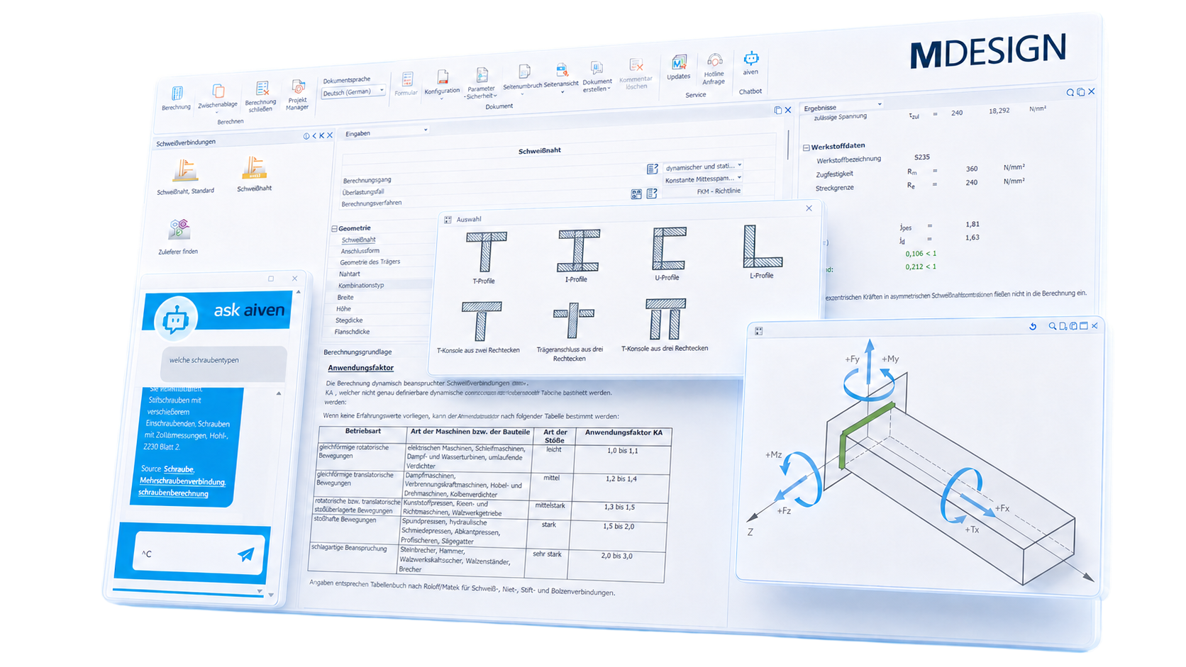
Accurately determine the stresses in a welded joint
Depending on the weld configuration and the direction of loading, different normal and shear stresses arise. Axial forces, transverse forces, and bending moments do not act in isolation but collectively determine the actual stress on the joint. MDESIGN combines these influencing factors in a structured weld analysis. This makes it possible to realistically simulate various welded joints, identify critical loads early on, and compare different variants in a targeted manner.
Incorporate material properties directly into the strength analysis
The load-bearing capacity of a welded connnections depends largely on the material used and its strength properties. Tensile strength, yield strength, fatigue properties, and other material-dependent parameters directly influence the permissible stress.
MDESIGN It provides a comprehensive database of steels and aluminum materials suitable for welding. Users can also add their own materials, internal property values, and company-specific material data for long-term use.
This allows standardized data and company-specific material standards to be integrated into a common calculation basis and applied consistently across various projects.
Evaluate static and dynamic strength separately
A welded connnections may be adequately sized for a single load but could still become critical under repeated load cycles. Therefore, especially under cyclic loading, it is not only the maximum stress but also the fatigue stress that determines the long-term load-bearing capacity.
MDESIGN supports both static and dynamic strength analyses and takes into account various load cases, notch cases, and load cycles.
This makes it possible to assess whether the weld will not only hold up in the short term but will also remain sufficiently strong throughout repeated operating cycles.
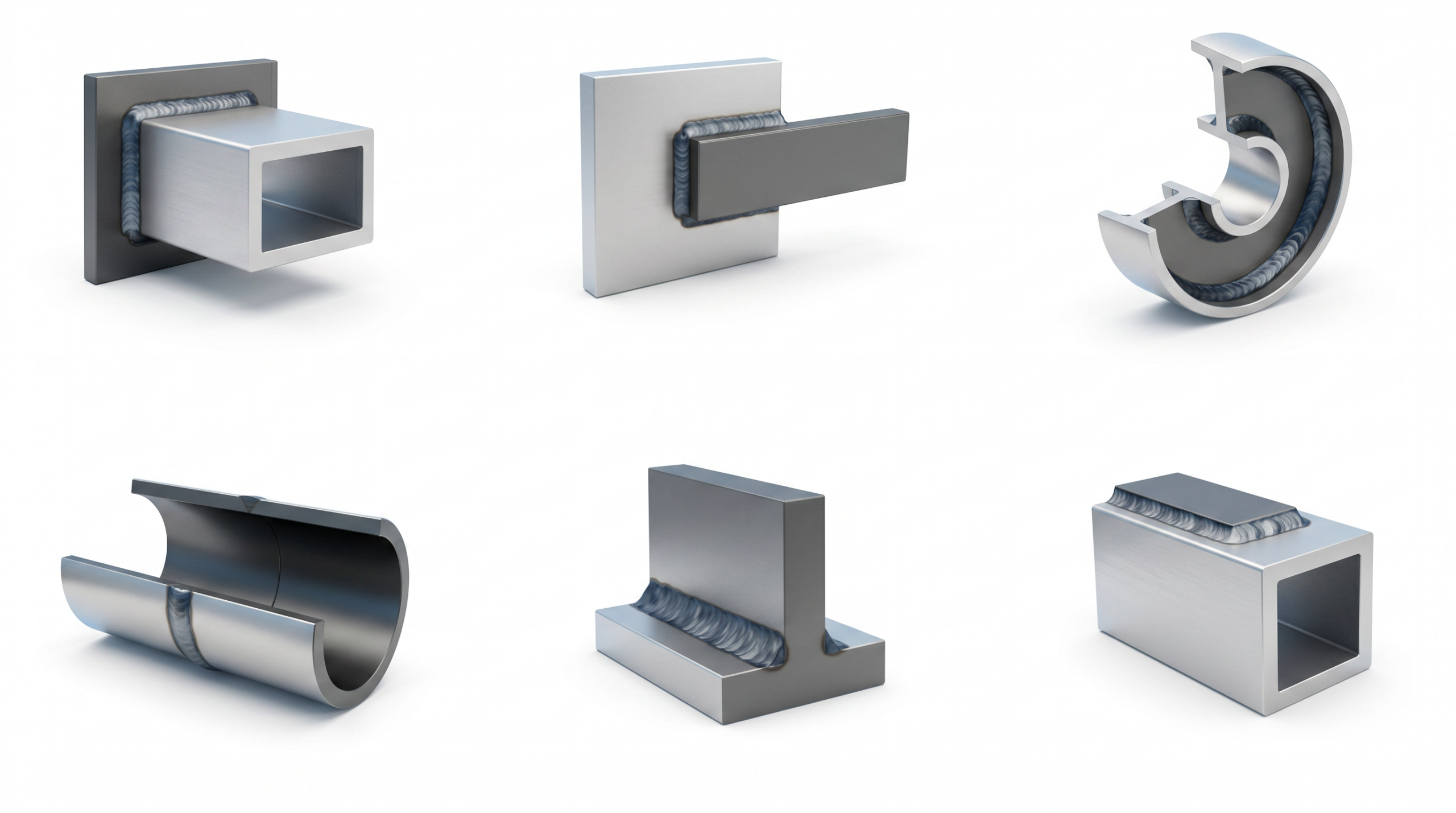
Understanding material utilization and targeted development of seam geometries
MDESIGN presents stresses, utilization rates, and verification results in a way that allows users to quickly grasp the technical relationships.
Based on this, designers can make specific decisions regarding further design: identify critical weld zones, adjust cross-sections, compare design variants, or avoid unnecessary oversizing. In this way, the strength analysis serves as a direct basis for further design development.
01
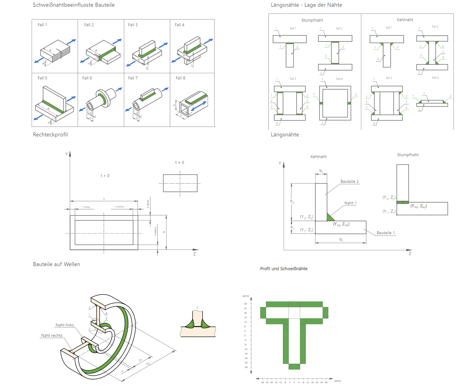
Automatically generated charts
Tabular analyses and graphical representations show which stresses govern the connection and how high the respective load is. This makes it possible to identify critical areas more quickly and to compare different design options in a targeted, technical manner.
|
02
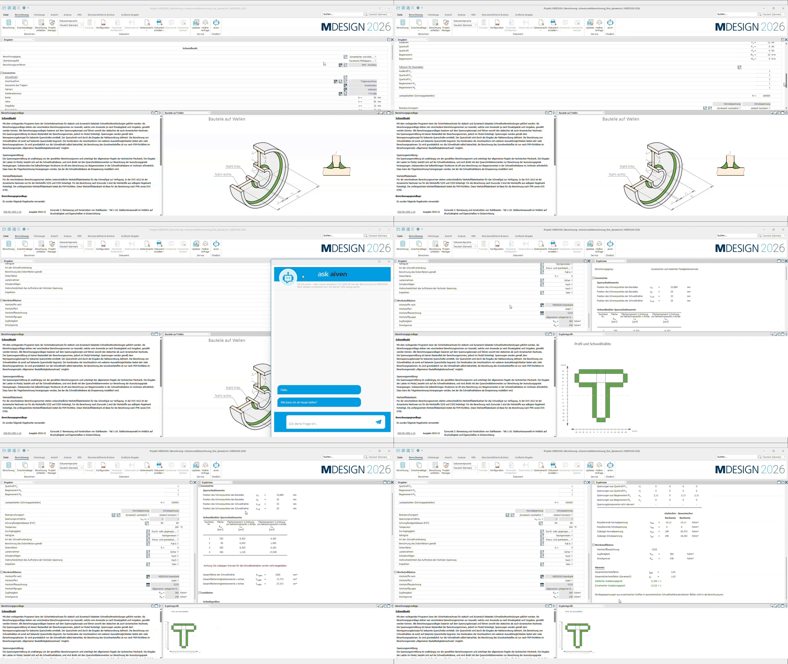
An intuitive approach to reliable weld bead calculation
The clearly organized interface, intuitive input options, help features, and built-in fundamentals make it easy to get started. AI assistance provides design engineers with support throughout the work process—even when weld verification isn't part of their daily responsibilities.
|
Documentation and proof at the touch of a button
Automatically generate technical documentation.
All input data, standards, boundary conditions, results, and graphics are automatically compiled into a complete set of documentation. This results in transparent verification documentation for internal development, customers, testing organizations, or manufacture.
Features of the MDESIGN weld calculation
The functions are organized concisely by code, connection types, inputs, materials, verifications, and results.
-
Standards & calculation bases
The calculation supports the key verification methods used in mechanical engineering, structural engineering, and rail vehicle manufacturing.
- DVS 0705
- DVS 1612
- Eurocode 3
- FKM guideline
- Static strength analysis
- Dynamic strength analysis
-
Joint types & weld types
The connection type and profile are selected to match the actual welded structure.
- Fillet and butt welds
- Beam connections and beam joints
- Bar connections and longitudinal seams
- Components on shafts
- Components affected by the weld bead
- Rectangular, round and hollow profiles
- Standard profiles and combined cross-sections
- Continuous seams
-
Geometry & loads
The input data represents the actual connection geometry and the corresponding load case.
Input values
- Width, height, length, and diameter
- Component thickness and weld thickness
- Positions and distances of the partial cross-sections
- Axial force
- Shear forces in two directions
- Bending moments about two axes
- Torsional moment
- Service and maximum load factors
- Number of oscillations and voltage ratio
Calculated Values
- Resulting internal forces
- Load distribution per section
- Focus on the component and seam group
- Total area of the welds
- First- and second-order area moments
- Torsional moment
- Moments of Inertia
- Key interfaces
-
Materials & verification parameters
Material properties, weld quality, and operational factors are taken into account in the strength analysis.
- Materials from the MDESIGN database
- Yield strength and tensile strength
- Steels and aluminum materials suitable for welding
- FAT classes and notch cases
- Weld quality and rating groups
- Temperature-dependent reduction factors
- Thickness correction factors
- Safety and partial safety factors
- Load assumptions and consequences of damage
-
Stress and strength analyses
The stresses are superimposed from the individual load components and evaluated at the relevant points along the weld.
Basis for calculation
- Normal stresses resulting from axial force
- Normal stresses due to bending
- Shear stresses from transverse forces
- Shear stresses due to torsion
- Mid-range, high-range, and upper-range tensions
- Static or dynamic verification
Test Results
- Resulting normal stress
- Resulting shear stress
- Maximum stress at the point under the greatest stress
- Static utilization factor
- Dynamic utilization rate
- Overall safety factors
- Rating against permissible voltages
-
Results & analyses
The key calculation results are presented in tabular and graphical form for technical evaluation.
- Internal forces and load factors
- Cross-section and seam parameters
- Stresses at the critical joints
- Permissible voltages
- Static and dynamic utilization rates
- Safety factors
- Guidance on exceeding threshold values
- Graphical representation of the profile and welds
- Additional module-specific result graphs
Try it for free – Your access to MDESIGN
Discover for free
Learn about the features
Just get started
No download, no installation
Full range of services
14 days of access to all sections