Technical Article Design & Calculation

Hirth-Gearings:
New Possibilities

From aircraft engines and turbines to machine tools: Planker gears are used wherever high torque, precision, and compact design come together. Yet calculating them, of all things, is anything but trivial.

In Focus ✓ Geometry ✓ Local stress ✓ Screw connection ✓ Load capacity

A tried-and-true combination. And a good reason to rethink how it’s calculated.

Planker gear systems have been technically established for decades. They combine high angular accuracy with high torque capacity and relatively low installation effort.

Nevertheless, their design is anything but trivial. This is because load-carrying capacity is not determined by a single point or a single stress value. Geometry, tooth root, tooth flank, bolting, preload, and load distribution all interact with one another. Anyone who wants to reliably evaluate such a connection must understand the system—not just solve a formula.

That is precisely what this technical article is about: What makes Plankerb gearings so mathematically challenging? Which points actually limit their load-carrying capacity? And how can a specialized calculation be turned into a structured development process that no longer relies on individual manual calculations or ad-hoc Excel spreadsheets?

The new " MDESIGN " module for Planker gearing makes this very step possible.

Why Planker gears are mathematically challenging

At first glance, the basic principle seems straightforward: Two components are connected to each other via a form-fit interlocking mechanism on their end faces and clamped together by one central screw or several decentralized screws.

The real challenge begins under actual load.

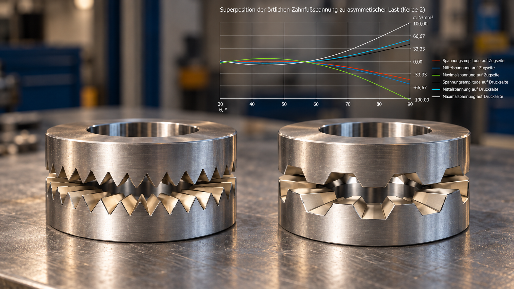
Two gear couplings with a stress diagram

In addition to torsion, axial force, shear force, and bending can occur simultaneously. The screws introduce additional preload forces into the system. The components and the bolted joint have different stiffnesses. Local notch stresses develop at the tooth root, and contact pressures develop on the flanks.

A design change therefore rarely affects just a single parameter. A different diameter alters the geometry and the effective lever arms. A different screw arrangement changes the force flow. Increased preload can stabilize the contact but simultaneously increases the stress on the bolted joint.

The underlying calculation methodology therefore takes into account not only torsional, axial, and combined loads, but also local tooth-flank stresses, stress distributions at the root radii of notches, and elastic deformations of the components.

That is precisely the difference between a single calculation and a genuine systems analysis.

What determines load-bearing capacity?

The highest stress does not necessarily occur where one might expect at first glance. Decentralized bolting, in particular, gives rise to localized effects that require a nuanced analysis.

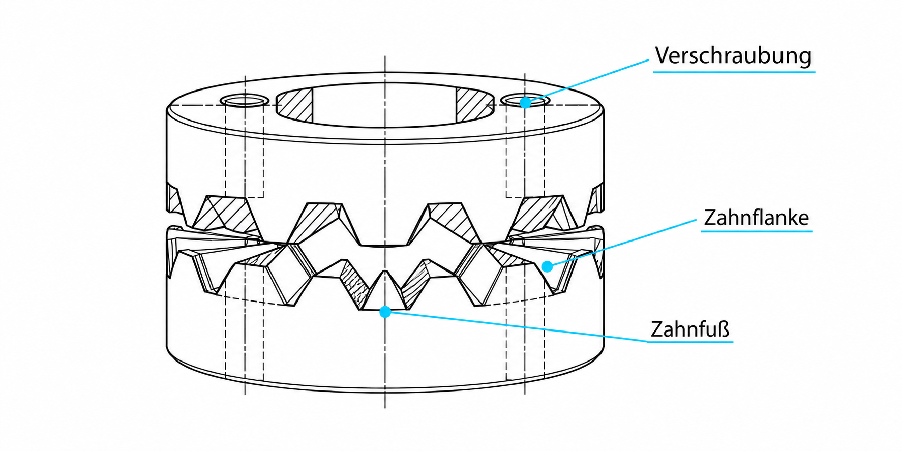
01

Tooth base

Local stresses result from several superimposed stress components.

02

Tooth flank

The local stress indicates just how much stress the contact zone is actually under.

03

Screw connection

Stiffness and preload help determine how loads are distributed between the screws and the gear teeth.

Technical toothed coupling with marked areas for the tooth base, tooth flank, and screw connection

Why a Scientific Foundation Is Crucial in This Context

In the case of a special joint subject to multiple superimposed loads, the question inevitably arises: How reliable is the calculation method used?

A key foundation is provided by the dissertation by Sebastian Grams at TU Dresden on the stress and load-carrying capacity of Planker gears with central and decentralized bolting. The dissertation presents a calculation method for the load-carrying capacity of the tooth root, tooth flank, and clamping bolts.

A key point here is that the methodology was not developed exclusively theoretically. The dissertation includes numerous experimental studies, including those on support effects and the influence of intermediate stress, which were also used to verify the load-carrying capacity analysis. The topic was also the subject of FVA Research Project 392 III on the stress and load-bearing capacity of Planker interlockings with decentralized bolted connections.

This means that the calculation is based on more than just a collection of appropriate equations. It is based on a scientifically developed and experimentally tested methodology . The new MDESIGN module makes this methodology usable for everyday practical calculations. The underlying doctoral dissertation forms the central basis for the calculations; in addition, approaches from the FKM guideline, among others, are used.

The crucial question is rarely just: “What is the voltage?”

At first glance, a single calculated value seems unambiguous. 420 N/mm². But is that a lot? Is it acceptable? Which part of the joint is actually critical? And would a design change actually relieve stress at that point, or would it simply increase stress elsewhere?

This is exactly where Plankerb gearing becomes interesting. The new MDESIGN module calculates local tooth root stresses on the tension and compression sides, taking into account different load components as well as additional effects such as ring expansion.

In versions with decentralized screw connections, additional local factors come into play, such as the bore diameter and bore location.

This shifts the relevant question from “What is my stress level?” to “Where does the critical stress occur, and what mechanism limits my Design?”

This question is much more valuable to the designer.

What if the result is correct, but no one knows what it means?

A modern calculation can produce a great many results.

However, that doesn't automatically solve the next problem: its interpretation.

Why is this notch critical?
Is a certain safety factor still sufficient?
What input causes the change?
And what parameter would be useful for improving the Design ?
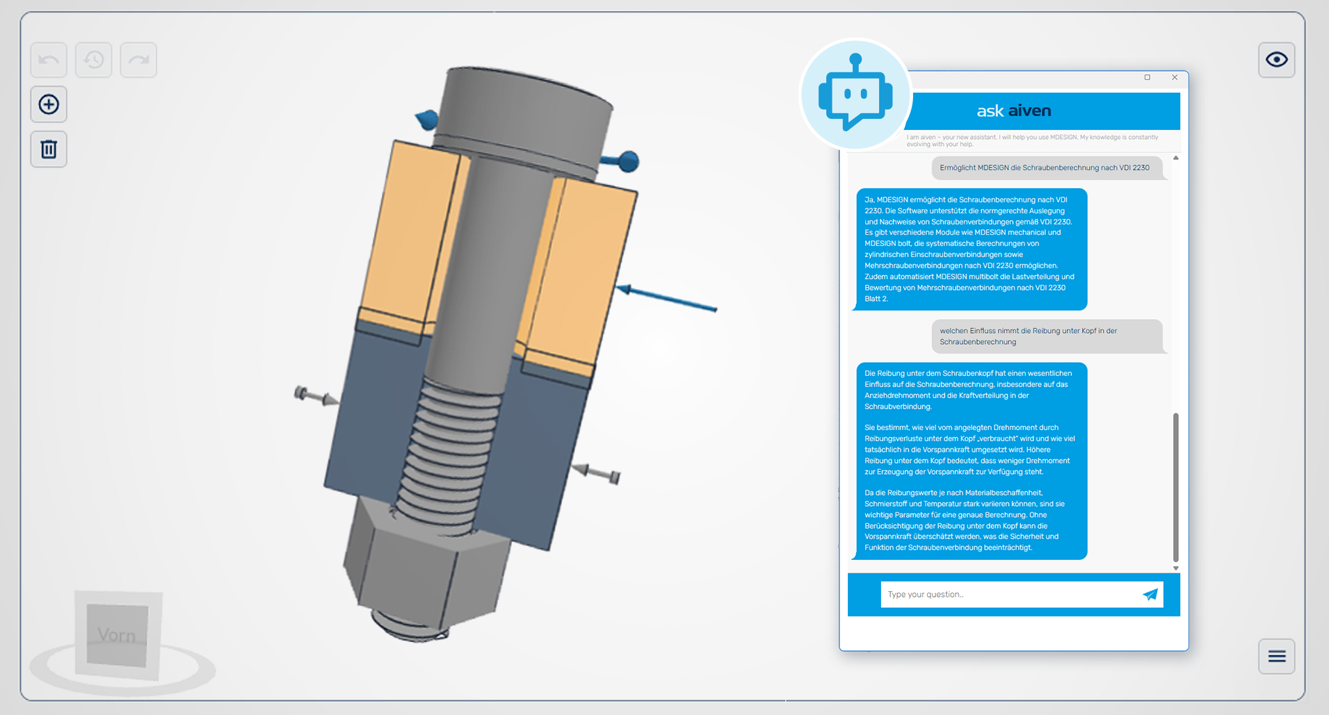
MDESIGN with 3D visualization and Aiven

This is exactly where the AI assistant MDESIGN aiven complements the calculation process.

Aiven can respond to specific calculation scenarios and answer questions about inputs, results, and technical contexts. This ensures that the technical decision is not delegated to AI; it remains with the design engineer.

But the gap between an eye-catching result and understanding it is getting smaller.

This is particularly relevant for more complex specialized calculations. After all, a tool is not considered good simply because it outputs a particularly large number of values.

It's good when users understand what they can do with them.

Why not just keep doing calculations by hand or using Excel?

Manual calculations and Excel models have their place in engineering—and rightly so.

They are flexible, transparent, and—especially when it comes to manageable tasks—often extremely efficient.

It becomes more difficult when a table evolves over the years into a separate calculation system .

Formulas must be maintained. Boundary conditions must remain known. Extensions must not alter existing dependencies without notice. The scope of validity must be understood. And at the very latest when the original developer is no longer available, a flexible solution quickly becomes a matter of knowledge.

This is not to say that Excel calculations are inherently unreliable.

It's all about reproducibility.

Is it clear which methodology was used?
Are the same assumptions applied to each variant?
Is all relevant supporting documentation included?
Can the results be clearly compared with one another?
And will the calculation still be understandable later on?

The more complex a connection becomes, the more valuable standardized inputs, defined calculation methods, and consistent evaluations become.

The new module does not replace the engineer's technical understanding.

However, it reduces the amount of work that has to be rebuilt, checked, and maintained each time.

The real gain does not come from the final proof

Perhaps that is actually where the module's greatest potential lies.

If a specialized calculation does not have to be recreated from scratch every time, it can be repeated more quickly.

And that’s precisely what makes the very thing interesting that is often overlooked in complex individual calculations:

Compare options.

What changes when the preload force is altered?
Which bolt arrangement is more favorable?
How does the tooth root respond to a geometric change?
Which variant has more reserve?
And is there a parameter to which the joint is particularly sensitive?

The calculation basis is also expressly intended for comparative calculations in the design phase as well as for service life estimates during operation.

This changes the timing of the calculation.

Not just: “ Design ’s in place. Will it hold?”

But even earlier: “Which Design should I even pursue?”

That is exactly where computation transforms from a monitoring tool into a development tool.

Recalculating Planker gears, therefore, does not mean reinventing their physics

The scientific basis is there. The connection itself has been proven. And the mechanical relationships remain the same as well.

What's new is how we deal with it.

MDESIGN transforms a specialized methodology into a structured calculation process for Hirth, Curvic-Coupling, and Zyklo-PalloidGearings. Geometry, load distribution, local stress, tooth flank, screw connection, and contact conditions can be analyzed within a single model.

This does not mean that the designer needs to understand any less.

On the contrary.

He gains more opportunities to systematically examine relationships, compare different options in a reproducible manner, and critically examine results.

Complexity doesn't go away. It just becomes more manageable.

Maybe it's worth making a comparison

Anyone who has previously designed Plankerb gearing using manual calculations, their own tables, or several separate verification methods does not have to simply discard their previous approach.

A direct comparison is much more interesting.

Set up the existing calculation scenario once in MDESIGN .

Use the same boundary conditions.

Compare the results.

And then, don't just check whether the numbers match, but also what additional connections become apparent.

Perhaps the module will confirm the previous interpretation exactly.

Maybe it points to another critical issue.

Perhaps a variant that has not yet been investigated at all due to the additional computational effort might prove interesting.

All three results would be a good reason to try a different approach to the calculation.

Calculate Planker gears yourself at MDESIGN

Model your own use case, compare variants, examine critical points, and use Aiven to analyze the results directly within the calculation context.

MDESIGN Try it for free.